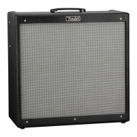
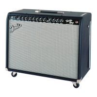
Do you have a question about the Fender HOT ROD DEVILLE 410 Combo and is the answer not in the manual?
| Brand | Fender |
|---|---|
| Model | HOT ROD DEVILLE 410 Combo |
| Category | Musical Instrument Amplifier |
| Language | English |
Confidential and proprietary information for qualified technicians regarding equipment maintenance and service.
Explains the coded naming conventions used for capacitors, resistors, and hardware in part descriptions.
Detailed list of parts for the printed circuit board assembly, including quantities, part numbers, descriptions, and reference designations.
List of components and parts required for the amplifier's chassis assembly, including hardware and connectors.
Components and parts list for the amplifier's cabinet, including speaker, grille, and mounting hardware.
Parts list for the footswitch, including buttons, diodes, LEDs, jacks, and resistors.
Includes covers, manuals, and schematics not categorized under other assembly lists.


 Loading...