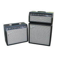
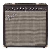
SUPER CHAMP X2 COMBO/HEAD™
(This is the model name for warranty claims)
ROUT signals are the input to the differential amp
which acts as a three pole active low pass filter for
de-emphasis. The output of U3-A is applied to a
buffer amp U1-A which drives op-amp U1-B which
provides the LINE OUT signal and the power amp
input. FET Q-1 provides system muting during
power up/down in conjunction with the power sense
circuits composed of D9, Q2, and Q4.
USER INTERFACE
The 4 – 16 position encoders (S2 – S3) for the
VOICE and EFFECT SELECT are sent to the GPIO
buss of the uDSP and polled at a 1000Hz rate.
The 6 potentiometers CH1 VOLUME (R85), CH2
VOLUME (R83), CH2 GAIN (R84), TREBLE (R82),
BASS (R81), and AND FX LEVEL (R80) generate
DC Voltages (0.0V to +3.3V) that are polled at a
1000Hz rate by the uDSP’s A/D converter.
POWER AMPLIFIER
The power amplifier consists of V1, V2, and V3. T2
and associated circuitry. The signal is fed to the
gate of V1-B in common cathode configuration. The
signal is then fed from the plate of V1-B to the gate
of V1-A which is operating as a phase splitter driv-
ing V2 from its’ plate and V3 from its’ cathode. V2
and V3 are operating in Class A-B push-pull mode.
T2 matches the impedance of V2’s plate to the 8
Ohm speaker. Negative feedback is provided by
R23 feeding signal back to V1-B’s cathode.
µDSP PCB
The µDSP PCB is located in the back of the chassis
opposite the power transformer. It provides the am-
plifier voicing and effects functions. The µDSP PCB
is not field serviceable and must be replaced as an
assembly.
USB PCB
The USB PCB provides the USB interface to the
µDSP and ESD protection. The USB interface is
used to communicate between the user’s computer
for the purpose of altering the amp’s presets or res-
toring the amp to factory settings.
POWER SUPPLY
T1 has four secondary windings for the +5V regula-
tor, the +/-12V supplies, the tube filaments and the
high voltage supply. The violet winding is rectified
by a fullwave bridge, filtered by C41 and fed to the
µDSP PCB where it is regulated to +3.3VDC and
fed back on to the main PCB. Similarly, the center
tapped orange and yellow winding is rectified, fil-
tered and fed to +/-12V zeners to provide power to
the operational amplifiers and other circuitry. The
red windings provide the high voltage for the va-
cuum tubes. The green winding provides 6.3VAC
for the vacuum tube filaments. A voltage doubler is
employed to produce -41.9VDC to bias the output
tubes, V2 and V3.
.