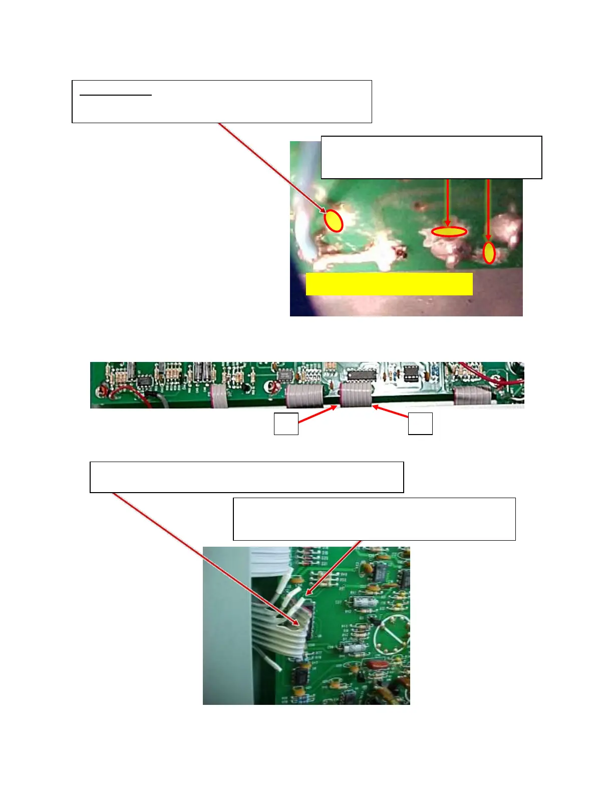
Figure 3 – R84
Figure 4
On ribbon cable PW3, the red-striped side is conductor #1 for our purposes.
Figure 5
FOR R84 ONLY: 1
A. Cut PCB trace where circled, between R84 terminal A and
the via (thru-hole in PCB) as shown in Figure 3.
B. Cut PCB traces (2 places – where circled)
above and next to terminal C, thus isolating
this terminal.
Separate the cut conductors from the rest of the ribbon and
install heat-shrink-tubing (HST) on each lead as shown in
Figure 5.
Near the middle of the ribbon cable (see Figure 5), cut conductors
#1, #2, #3, and #8 (#8 being the farthest from the red striped side).













 To Next Page