Ifthemoulded3-pinplugattachedtotheunitis
damaged and needs replacing, it is important that
it is correctly destroyed and replaced by an
approvedBS1363/5Afusedplugandthatthe
following wiring instructions are followed.
The wires in the mains cable are coloured in
accordance with the following code:
blue neutral
brown live
As the colours of the wires in the mains cable of
the unit may not correspond to the coloured
markings identifying the terminals in the plug,
proceed as follows:
- The wire which is coloured blue must be
connected to the terminal which is marked with
theletterNorcolouredblack.
- The wire which is coloured brown must be
connected to the terminal which is marked with
theletterLorcolouredred.
TECHNICAL DATA
AGM1043
Mainsvoltage V~ 230
Mainsfrequency Hz 50
Power input W 880
No-loadspeed min
-1
11,000
Grinding disc
Diameter mm 125
Bore mm 22.2
Spindlethread M14
Weight kg 2.2
NOISE AND VIBRATION
AGM1043
Soundpressure(L
pa
) dB(A) 87.7
Acousticpower(L
wa
) dB(A) 98.7
Uncertainty(K) dB(A) 3
Vibration m/s
2
7.52
Uncertainty(K) m/s
2
1.5
2
Wear hearing protection.
Vibration level
The vibration emission level stated in this instruction
manual has been measured in accordance with a
standardisedtestgiveninEN60745;itmaybeused
to compare one tool with another and as a
preliminary assessment of exposure to vibration
when using the tool for the applications mentioned
- using the tool for different applications, or with
different or poorly maintainted accessories,
maysignicantlyincreasetheexposurelevel
- the times when the tool is switched off or when
it is running but not actually doing the job, may
signicantlyreducetheexposurelevel
Protect yourself against the effects of vibration by
maintaining the tool and its accessories, keeping
yourhandswarm,andorganizingyourwork
patterns
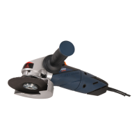
Your angle grinder has been designed for grinding
and cutting masonry and steel.
1. On/offswitch
2. On/offswitchlock
3. Spindlelockbutton
4. Spindle
5. Guard
6. Maingrip
7. Auxiliary grip
8. Carbon brush indicator
ASSEMBLY
4
Before assembly, always switch off the
machine and remove the mains plug
from the mains.
Mounting and removing the grinding disc
2
Never attempt to remove the guard.
Mounting
● Placethemachineonatablewiththeguard
(5) facing upwards.
● Mountthespacer(9)ontothespindle(4).
● Mountthegrindingdisc(10)ontothespindle(4).
● Keepthespindlelockbutton(3)pressedand
rmlytightenthetensionnut(11)usingthe
spanner (12).
Removing
● Placethemachineonatablewiththeguard
(5) facing upwards.
● Keepthespindlelockbutton(3)pressedand
loosen the tension nut (11) using the spanner
(12).
● Removethegrindingdisc(10)fromthespindle
(4).