18 Ferm
HYDRAULIC BODY REPAIR SET
SAFETY INSTRUCTIONS
The following pictograms are used in these instructions
for use:
Denotes risk of personal injury, loss of life or
damage to the tool in case of non-observance of the
instructions in this manual.
Carefully read this manual before using the machine.
Make sure that you know how the machine functions and
how to operate it. Maintain the machine in accordance with
the instructions to make sure it functions properly. Keep this
manual and the enclosed documentation with the machine.
ADDITIONAL SAFETY INSTRUCTIONS
Fig.6
A. Never exceed the maximum load capacity of the ram.
Do not over extend the ram, as it is possible to force
the plunger out of the top of the ram.
B. When coupler valves are disconnected always insert
the dust cap to keep the oil lines clean.
C. If the load is not centered to the ram plunger, pump
carefully. If you have to use excessive pressure to
pump the ram, stop the operation and adjust the set-
up so that the load is more central. This should decre-
ase the effort required.
D. Do not drop any heavy objects onto the hose, and do
not allow the hose to kink. Always allow clearance
for the hose to avoid damage to the hose and coup-
lers.
E. Keep the equipment away from heat or fire, as this
may damage or weaken the equipment.
USE
ATTACHMENT COMBINATIONS
Fig.1 - 5
• The pump unit can be used with the multi-directional
ram. (see Fig.1)
• For confined areas the hydraulic spreading wedge
should be used. (see Fig.2)
• Fig.3 shows a few of the many attachment combina-
tions.
1. Connect the hydraulic ram and pump unit hose
together, ensure you have securely fastened the
couplings before pumping.
2. Firmly close the releast valve by turning it in a clock-
wise direction (See Fig .4, A).
3. Apply pressure to the pump by pumping the handle
up and down.
4. To release the pressure turn the valve anti-clockwise
(See Fig .4,B).
The pump can be used in any position, but always
keep the hose end of the pump unit facing down-
wards when positioned vertically (See Fig .5).
TROUBLE SHOOTING
1. Pump unit will not work
Dirt on valve seals/Worn seals.
• Replace with new seals.
2. Pump unit will not produce pressure
Air block
• Open the release valve and remove oil filler plug.
The reservoir could be overfilled or low on hydraulic
oil level.
• To check the oil level, remove the filler plug. Top up oil
to correct level.
3. Pump unit feels unsteady under load
Air block.
• Pump handle a couple of full strokes and close the
release valve.
The pump cup seal could be worn out.
• Replace the cup seal with a new one.
4. Pump unit will not lower completely
Air block
• Replace filler plug
• Release air by removing filler plug.
Ferm 3
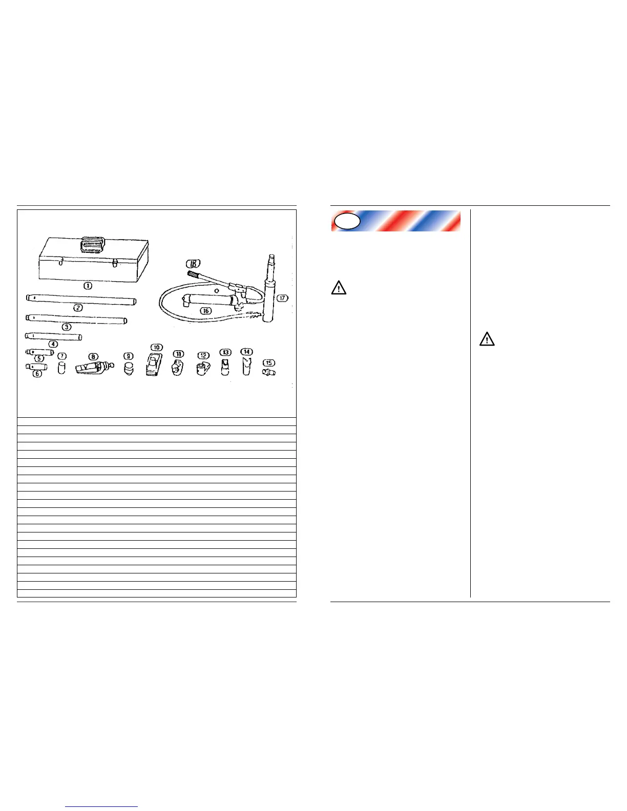
SPARE PARTS FOR HB-4
REF NR DESCRIPTION FERM NR
2 495 MM EXTENSION BAR 104059
3 418 MM EXTENSION BAR 104061
4 215 MM EXTENSION BAR 104062
5 125 MM EXTENSION BAR 104063
6 82 MM EXTENSION BAR 104064
7 SERRATED CAP, 1/2 TON 104069
8 SPREADING WEDGE 104058
9 RUBBER HEAD 104070
10 BASE PLATE 104060
11 RAM TOE 104071
12 PLUNGER TOE 104072
13 CLEFT CAP 104073
14 “V” BASE 104074
15 HOLE CON NECTOR 104075
16 4 TON PUMP UNIT 104056
17 RAM UNIT 104057
18 HYDRAULIC HOSE 104067
- HOSE/UNIT CONNECTION BOLT 104065
- NUT FOR CONNECTION BOLT 104066
- REPAIR KIT 104068
EXPLODED VIEW HB-4
 Loading...