6
EN
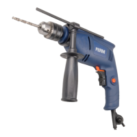
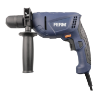
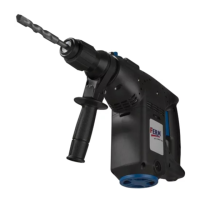
DESCRIPTION (FIG. A)
Your impact drill has been designed for drilling
holes in wood, metal and plastics and for hammer
drilling in brick and concrete.
1. On/off switch
2. Lock-on button
3. Speed adjustment wheel
4. Forward/reverse switch
5. Switch for drilling / hammer drilling
6. Chuck
7. Main grip
8. Auxiliary grip
9. Depth stop
10. Chuck key
11. Chuck key holder
ASSEMBLY
Before assembly, always switch off the
machine and remove the mains plug from
the mains.
Mounting and removing the drill bit (fig. B)
The machine is suitable for use of the following
drill bits:
- Wood (HSS)
- Metal (HSS)
- Concrete / masonry (hard metal)
Mounting
• Place the chuck key (10) into one of the holes
in the chuck (6).
• Open the chuck (6) by turning the chuck key
(10) counterclockwise.
• Insert the drill bit (12) into the chuck (6).
• Close the chuck (6) by turning the chuck key
(10) clockwise.
• Remove the chuck key (10) from the chuck (6).
Removing
• Place the chuck key (10) into one of the holes
in the chuck (6).
• Open the chuck (6) by turning the chuck key
(10) counterclockwise.
• Remove the drill bit (12) from the chuck (6).
• Close the chuck (6) by turning the chuck key
(10) clockwise.
• Remove the chuck key (10) from the chuck (6).
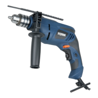
Mounting and removing the auxiliary grip (fig.C)
Mounting
• Loosen the auxiliary grip (8).
• Slide the auxiliary grip (8) over the chuck (6).
• Turn the auxiliary grip (8) to the required
position.
• Tighten the auxiliary grip (8).
Removing
• Loosen the auxiliary grip (8).
• Remove the auxiliary grip (8) from the chuck (6).
• Tighten the auxiliary grip (8).
Mounting and removing the depth stop (fig. D)
The depth stop is used to set the maximum
drilling depth.
Mounting
• Loosen the auxiliary grip (8).
• Insert the depth stop (9) through the hole in the
auxiliary grip (8).
• Set the depth stop (9) to the required position.
• Tighten the auxiliary grip (8).
Removing
• Loosen the auxiliary grip (8).
• Remove the depth stop (9) from the auxiliary
grip (8).
• Tighten the auxiliary grip (8).
USE
Switching on and off (fig. A)
• To switch on the machine, press the on/off
switch (1). The further the on/off switch (1) is
pressed, the higher the speed of the machine.
• To switch the machine to continuous mode,
keep the on/off switch (1) pressed and
simultaneously press the lock-on button (2).
• To switch off continuous mode, press the on/
off switch (1) again.
• To switch off the machine, release the on/off
switch (1).
Forward/reverse switch (fig. A)
Do not change the direction of rotation
during use.