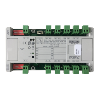
Bs, -: for the connection of a hall exit button to open the door.
+12: 12 Vdc auxiliary output (max: 300 mA).
C, No, NC: Potential free relay contacts. 250 Vac / 30 Vdc - 3A. Max.
ON: LED indicating that the relay has been activated.
TECHNICAL SPECIFICATIONS
DESCRIPTION
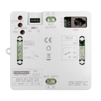
JP1: Work mode selector
• GE: GENERAL ENTRANCE mode
• BL: BLOCK mode
TERMINAL STRIPS
• +12: 12 Vdc auxiliary output (max: 300 mA).
• C, No, NC: Potential-free relay contacts. 250 Vac / 30 Vdc - 3A. Max.
• ON: LED (Green) indicating that the relay has been activated.
BUS INPUT: Connection strip to the DUOX PLUS Bus.
PRG BUTTON : To enter PROGRAMMING mode and define the ACTIVATION TIME.
EXTERNAL PUSH BUTTON CONNECTIONS: By shorting BS and -, the relay will activate for the configured ON TIME.
INDICATIVE LEDs:
• PWR (Red): Indicates that the device receives the necessary power to work.
• MODE (Blue): Indicates if the device is in PROGRAMMING mode and the stage of the procedure it is in.
QR TO THE USER GUIDE : when scanning this QR with the mobile, it takes the installer to the technical manual of the product.
TECHNICAL CHARACTERISTICS
Power supply: 18-24 Vdc
Consumption:
Standby: 1.2 W
Relay ON: 7.2 W
Operating temperature: [-5ºC, + 40ºC]
Relative humidity: [5%, 95%]
Dimensions: 86 (height) x 106 (width) x 31 (depth) mm
DIN 6 rail mounting (including side fixing brackets to screw, width 106 mm). Eliminating the lateral fixing brackets for the
screws the width is 89 mm (DIN 5).