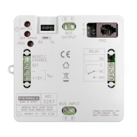
The DUOX Video Amplifier is a core component of the Fermax DUOX system, designed to manage and enhance video and audio communication within an intercom setup. It serves as a central hub for panel settings, configuration, and call extension modules, ensuring seamless operation and clear communication.
Function Description
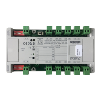
The DUOX Video Amplifier primarily functions as an interface and control unit for DUOX video intercom systems. It integrates various panel settings, including camera LEDs, language selection for "door open" messages, and audio adjustments for monitors, panels, and the open door function. The amplifier also manages microphone connections and provides panel connectors for the DUOX Bus, relay contacts for lock-release, 12Vdc output, entrance hall button, and door sensor input. Its core role is to amplify and distribute video and audio signals, ensuring reliable communication between the outdoor panel and indoor monitors.
Usage Features
The amplifier offers a range of user-friendly features for configuration and operation.
Panel Settings:
- Camera LEDs: Indicates when the camera is active (LEDs ON) or always off (LEDs OFF).
- Language Selection: Allows users to choose the language for the "door open" warning message from a wide array of options, including Spanish, English, French, Dutch/Flemish, German, Catalonian, Valencian, Balearic, Portuguese, Basque, Galician, Greek, Polish, Czech, Slovak, Turkish, Chinese, Persian/Farsi, Arabic, Norwegian, Finnish, Swedish, Danish, Icelandic, Russian, Italian, Hindi, Hungarian, Hebrew, Croatian, and French (LONG). It also includes options for "campana" (bell) and deactivation.
- Audio Settings: Provides adjustments for the audio levels of the monitor, panel, and open door.
- Microphone Connection: Dedicated connection for the microphone.
- Panel Connectors:
- B,B (DUOX Bus): Handles telephone/monitor power, data, audio, and video signals.
- C, NO, NC: Relay contacts for lock-release connection (2A@30Vdc).
- +12: Provides 12 Vdc-250mA output (max 500mA for 100 seconds).
- BS, -: Connects to the entrance hall button.
- S, -: Connects to the door sensor input.
- +, GND: Reserved for future versions.
- P1, P2: Button connection.
Configuration Methods:
The DUOX Video Amplifier supports two primary configuration methods: Voice Assisted Configuration for Button Panels and Configuration Table for Direct Panels.
This method uses voice messages from a synthesizer (available in Spanish, English, French, German, Italian, and Portuguese) to guide the user through the configuration process.
- Accessing Configuration: Press the SW1 button 4 times. The amplifier will announce "CONFIGURATION" and begin the process.
- Exiting Configuration: Press and hold SW1 for 5 seconds, or it will automatically exit after 30 seconds of inactivity.
- Parameter Navigation: Pressing SW1 advances through parameters, with the amplifier announcing the currently configured parameter and its value.
- Changing Values: Press any call button to change the value. Each press increases the value, accompanied by a BEEP. After 5 seconds of no button press, the new value is announced. When the maximum value is reached, a BOOP sounds, and the value resets to the minimum.
- Resetting Parameters: Pressing a call button for 5 seconds triggers a BOOP, resetting the parameter to its minimum level or default value.
The configuration diagram illustrates the flow, covering parameters like Panel Number, Door Opening Time, Exit Button Time, Block Number, Sub-Block Number, Confirmation Phone Volume, Panel Type, Sensor Time, Reset Guard Unit Mode, and Zoom.
Configuration Table in Direct Panel:
This method uses a keyboard for configuration.
- Accessing Programming: Enter "A + 4444" (default programming access code). A confirmation tone (beep-beep) indicates successful entry.
- Configurable Parameters:
- Time activ. lock releases (01): Adjusts relay activation time for lock releases from home or access control (default: 3 seconds).
- Time activ. exit button (02): Adjusts relay activation time for lock releases from the exit button (terminals Bs y -) (default: 6 seconds).
- Panel type (03): Configures the panel type as Sub-Block, Block, or General Entrance (default: Sub-Block).
- Block N° (04): Sets the block number for the panel (default: 0).
- Sub-Block N° (05): Sets the sub-block number for the panel (default: 0).
- Panel N° (06): Sets the panel number (default: 0).
- Door sensor time (07): Sets the maximum time the door can remain open once activated (default: 000 inactive).
- Opening code (08): Sets the 4-digit opening code from the keyboard (default: 0000 inactive).
- Programming code (09): Sets the code to access programming (default: 4444).
- MASTER panel (10): Activates the panel as master for programming home terminals (default: No).
- Caretaker Mode (11): Resets to night mode by entering "1" (default: No Reset).
- Monitor Volume (12): Adjusts the volume of the panel monitor (default: 5).
- RESET settings (13): Returns to default settings by entering "1" (default: No Reset).
- Focus the camera (14): Selects one of the video screens (0-9) for camera focus adjustment (default: 9).
- Entering Values: Enter the two digits of the parameter position, followed by the desired value (1, 2, 3, or 4 digits). A beep-beep confirms correct entry, while a boop indicates an error.
- Exiting Programming: Press 'A' when introducing the position number, or it will automatically exit after 60 seconds of inactivity with a beep-beep tone.
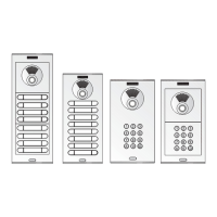
Call Extension Module Connection (Ref. 2441):
The amplifier supports internal wiring for call extension modules, allowing for systems with more than 16 pushbuttons. Modules can be daisy-chained, connecting "ARRIBA/UP" (up) and "AX" (axis) terminals to expand the number of call buttons. For multiple modules, the "SIGUIENTE/NEXT" (next) and "ANTERIOR/PREVIOUS" (previous) terminals are used to link them to the amplifier.
Maintenance Features
The DUOX Video Amplifier includes features for resetting settings to ensure proper functioning and troubleshooting.
RESET Settings:
- RESET Mapping (code for call button):
- Remove the power supply.
- While pressing the SW1 button, plug in the power supply and continue pressing SW1 for 5 seconds. The LED will blink rapidly, indicating that the button mapping has been restored.
- RESET of settings to factory default values (by keyboard):
- Direct Panel: Introduce specific numerical values via the keyboard.
- Pushbutton Panel: Temporarily connect a keyboard (ref. 7439) to enter numerical values. This involves connecting a 5-channel cable from the amplifier's CN1 to the keyboard's CN1, leaving the rightmost pin free. For Skyline panels, a 6-channel cable is used.
These maintenance features allow for easy restoration of default settings or remapping of call buttons, simplifying troubleshooting and system adjustments.