IT
FX
108
EN
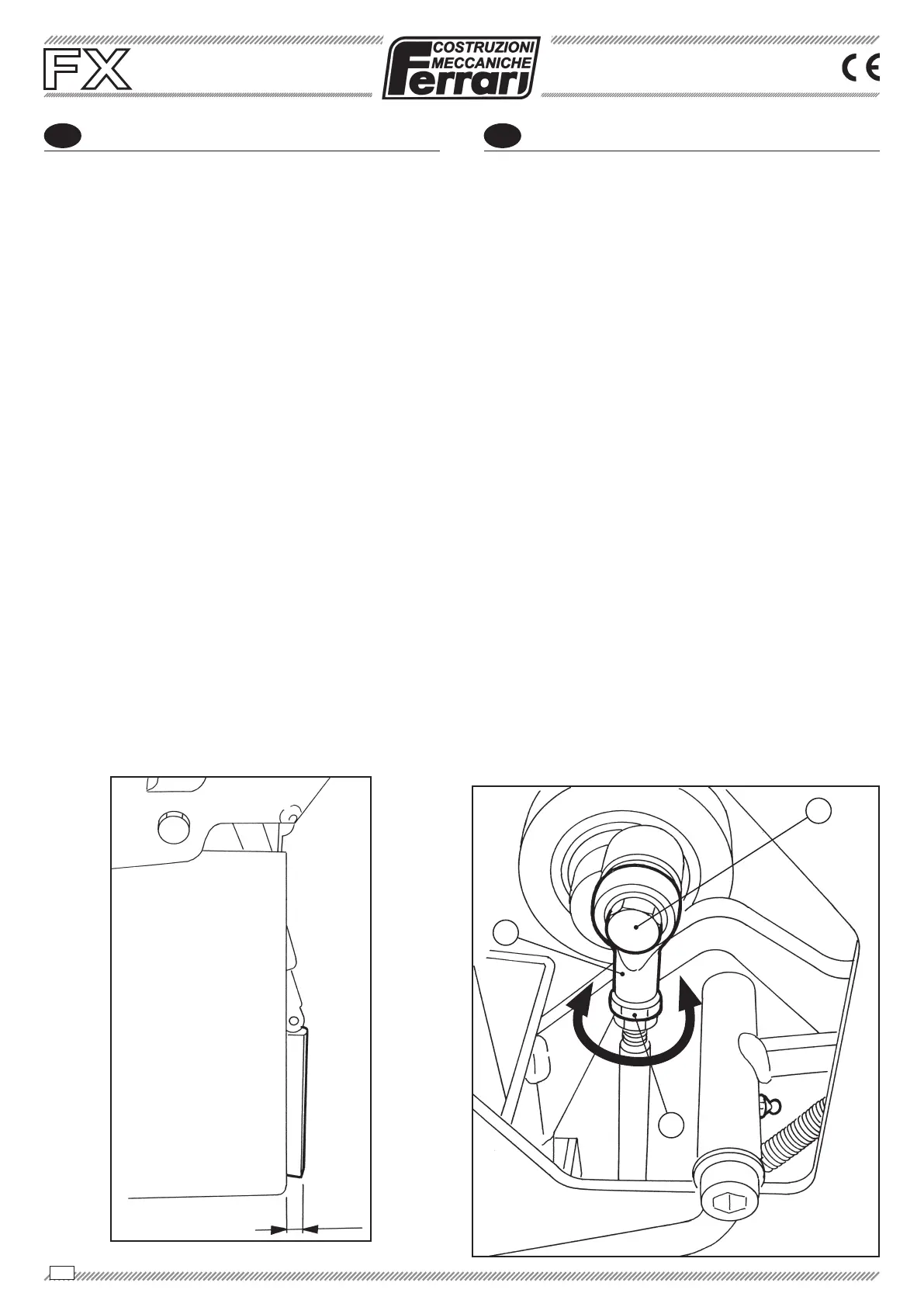
REGOLAZIONE USCITA ESTREMITÀ IN-
FERIORE MARTELLETTO ESPULSORE
Per un corretto lavoro, il martelletto espulsore deve
fuoriuscire dal vomere di 5-8 mm come indicato in
Fig. 1
snodo (A) allentando il dado (B), svitare il bullone (C)
la distanza, ruotarlo in senso orario per diminuirla,
(C) e stringere
il dado (B).
SOSTITUZIONE MARTELLETTO
ESPULSORE
Togliere il vomere rimuovendo le due viti (D), poste
da ambo i lati.
Togliere le due viti (E) da ambo i lati.
Togliere la vite (F) e a questo punto il martelletto
esce ed è quindi possibile sostituirlo.
SOSTITUZIONE BOCCOLE E PERNO
PUNTA ESPULSORE
Allentare la vite (G) con un cacciavite.
Rimuovere il perno (H).
Rimuovere le boccole (I) e mettere quelle nuove
(G).
A
C
5-8
mm
ADJUSTMENT OF EXPELLER HAMMER
LOWER END OUTLET
For a correct work, the expeller hammer must protrude
5-8 mm from the plough, as indicated in Fig. 1. To
modify this measurement, act on the rod (A) by loose-
ning the nut (B), loosen the bolt (C) and rotate the slot
clockwise to increase the distance or anti-clockwise
to reduce it, after the operation, put the bolt back (C)
and tighten the nut (B).
REPLACEMENT OF THE EXPELLER
HAMMER
Remove the plough, loosening the two screws (D),
placed on both sides.
Remove the two screws (E) from both sides.
Remove the screw (F). At this point, the hammer is
removed and so it can be replaced.
REPLACEMENT BUSHINGS AND PIVOT
POINT EJECTOR
Loosen the screw (G) with a screwdriver.
Remove the pin (H).
Remove the bushings (I) and put the new ones
the new pin and secure it with the screw (G).
B
Manuale d’uso e manutenzione
Operating and service manual
Mode d’emploi et d’entretien
Manual de uso y mantenimiento
TRAPIANTATRICE TRAINATA
TOWED TRANSPLANTING MACHINE
PLANTEUSE REMORQUÉE
TRASPLANTADORA REMOLCADA