12 ferrismowers.com
4
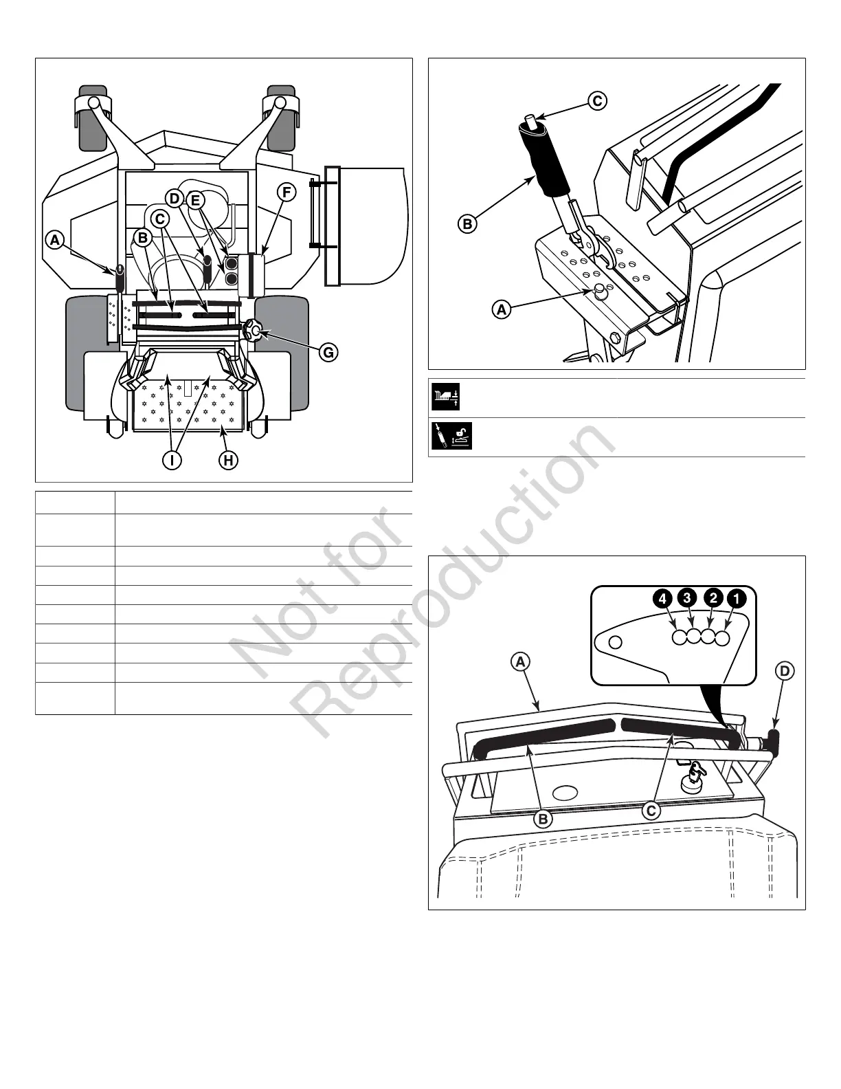
Callout Description
A Deck Lift Lever, Cutting Height Adjustment Pin, and Deck
Lift Release Button
B Maximum Forward Speed Bar
C Ground Speed Control Levers
D Parking Brake
E Transmission Oil Fill (Transmission Oil Reservoirs)
F Battery Box
G Fuel Tank Cap
H Operator Platform
I Transaxle Release Levers (Located on the rear of the
engine deck)
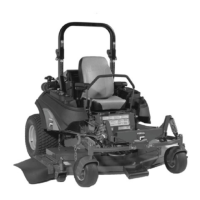
Deck Lift Lever, Cutting Height Adjustment Pin, and Deck
Lift Release Button: The deck lift lever (B, Figure 5), cutting
height adjustment pin (A) and deck lift release button (C), are
used together to control the cutting height of the mower deck.
See Cutting Height Adjustment for instructions on using these
controls.
5
Cutting Height Adjustment Pin
Deck Lift Lock Lever
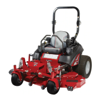
Maximum Forward Speed Bar: This unit is equipped with an
adjustable Maximum Forward Speed Bar (A, Figure 6), which
is located in front of the Ground Speed Control Levers (B &
C).
6
The Maximum Forward Speed Bar can be adjusted in four
different positions to suit the desired maximum forward speed
of the operator. The positioning hole closest to the ground
speed control levers (labeled as #1 in Figure 6) is the slowest
setting and the positioning hole furthest from the ground
speed control levers (labeled as #4) is the fastest.
To adjust the position of the Maximum Forward Speed Bar
pull the T-handle knob (D) out to release the maximum