36 www.ferrismowers.com
41
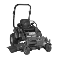
Seat Adjustment Knob (Suspension/Ride Comfort): The
seat adjustment knob (B) adjusts the suspension of the seat
(ride comfort). Turn the adjustment knob until the display
scale has a reading that matches the weight of the operator.
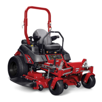
Ground Speed Control Lever Adjustment
The control levers can be adjusted in three ways. The
alignment of the control levers, the placement of the control
levers (how close the ends are to one another), and the
height of the control levers can be adjusted.
To Adjust the Control Lever Alignment
Loosen the mount bolts (A, Figure 42) and pivot the control
lever(s) (C) to align with each other.
42
To Adjust the Control Lever Placement
Loosen the jam nuts and adjust the placement bolt (B) in or
out to properly adjust the control lever end spacing.
To Adjust the Control Lever Height
Remove the mounting hardware and position the control lever
either up or down from its original position. You will need to
adjust the control lever alignment as described above.
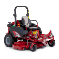
Speed Balancing Adjustment
If the unit drifts to the right or left when the ground speed
control levers are in the maximum forward position, the top
speed of each of these control levers can be balanced by
turning the adjustment bolt(s) (A, Figure 43). Only adjust the
speed of the wheel that is traveling faster.
43
To Reduce the Speed of the Faster Wheel
1. Loosen the securing nut (B).
2. Turn the top speed adjustment bolt counter-clockwise to
reduce the speed.
3. Tighten the securing nut when adjustment is complete.
WARNING
Unsafe Operation Hazard.
DO NOT adjust the unit for a faster overall speed forward or
reverse than it was designed for.
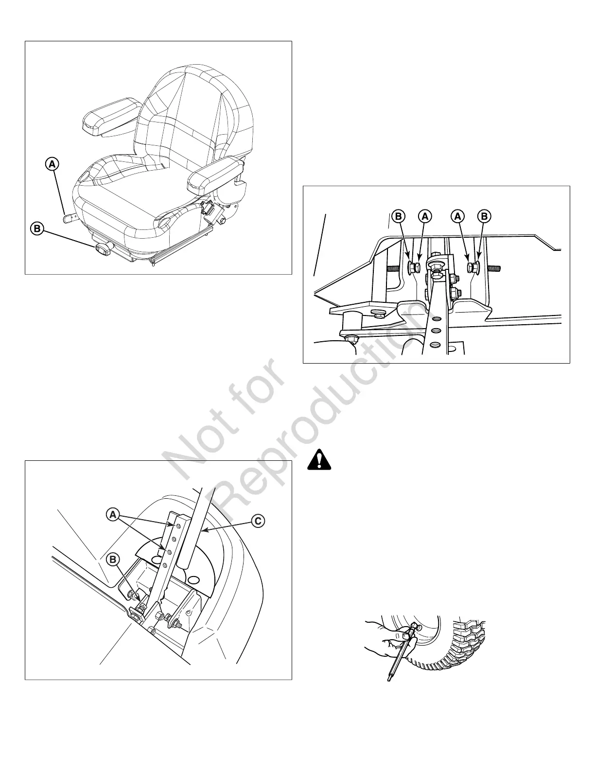
Checking Tire Pressures
Tire pressure should be checked periodically, and maintained
at the levels shown in the Specifications chart. Note that
these pressures may differ slightly from the "Max Inflation"
stamped on the side-wall of the tires. The pressures shown
provide proper traction and extend tire life.
Cutting Height Adjustment
The cutting height adjustment pin (A, Figure 44) controls
the mower's cutting height. The cutting height is adjustable
 Loading...