Do you have a question about the Ferroli OMNIA S 3.2 and is the answer not in the manual?
Explains the different hazard symbols used in the manual for safety.
Details minimum floor area requirements based on refrigerant charge and ventilation.
Specifies unsuitable installation sites to prevent hazards and ensure proper operation.
Details electrical wiring standards, RCD requirements, and pre-installation checks.
Covers safety procedures for servicing, handling refrigerants, and leak detection.
Provides guidance on transporting, storing, and disposing of the unit and its components.
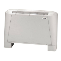
Details the system's capabilities for heating, cooling, and DHW production.
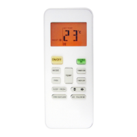
Describes the digital controller, its display, and basic controls.
Explains functions like DHW, Antilegionella, Eco, and Smart Grid integration.
Provides detailed technical specifications for various unit models.
Presents energy efficiency data and heat pump operating limits.
Shows available static pressure from the internal circulator.
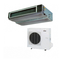
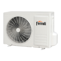
Illustrates the physical dimensions and connection points of the unit.
Shows the internal hydraulic layout and refrigerant circuit paths.
Provides example system configurations and a key for diagram symbols.
Guides on inspecting the unit upon arrival and selecting a suitable installation site.
Details refrigerant and hydraulic pipe limits, connections, and water circuit setup.
Covers refrigerant leak testing, air purging, and filling the water circuit.
Details electrical data, connections, grounding, and wiring requirements.
Illustrates wiring for thermostats, heaters, pumps, and additional heat sources.
Explains the user interface keys, display, and icons for operation.
Guides on setting operating modes (Heat/Cool) and temperature setpoints.
Details user menu functions for scheduling, DHW settings, and options.
Provides access to error codes, parameters, and system information.
Explains dip switch configuration and accessing the service menu.
Lists and explains various service parameters for system setup.
Covers test run functions and input signal definitions.
Explains selecting and using climatic curves for heating and cooling modes.
Details how to set custom climatic curve 9 for heating and cooling.
Provides guidance on troubleshooting common issues and identifying symptoms.
Lists all error codes, their causes, and corrective actions.
Outlines preliminary checks before initial heat pump operation.
Covers general maintenance tasks and checks for unit availability.
Details checks for the electrical cabinet and residual risks.
Provides instructions on safely accessing internal components.
Illustrates the electrical wiring for indoor unit models 10-16 (1ph) and 16T (3ph).
Explains the symbols and components shown in the refrigerant diagram.
| Brand | Ferroli |
|---|---|
| Model | OMNIA S 3.2 |
| Category | Air Conditioner |
| Language | English |