EasyManua.ls Logo

Ferroli OMNIA S HYBRID H 3.2 User Manual

Ferroli OMNIA S HYBRID H 3.2
88 pages
To Next Page IconTo Next Page
Page #1 background imageLoading...
Page #1 background image
.0
65
O
-
F
R
I
E
N
R
E
F
R
I
G
E
R
A
N
T
G
A
S
R32
D
L
Y
E
C
Cod. 3542B230 - Rev. 00 - 02/2022
INSTALLATION, USE AND MAINTENANCE MANUAL
EN
OMNIA S HYBRID H 3.2
INDOOR WALL UNIT FOR SPLIT REVERSIBLE HYBRID HEAT PUMPS
WHICH CAN BE COMBINED WITH AN OUTDOOR DHW HEATER
3542B230

Table of Contents

Question and Answer IconNeed help?

Do you have a question about the Ferroli OMNIA S HYBRID H 3.2 and is the answer not in the manual?
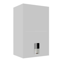
Ferroli OMNIA S HYBRID H 3.2 Specifications

General IconGeneral
MountingWall-mounted
Nominal heat output3.2 kW
Efficiency classA
Modulation1:10
Max working pressure3 bar
Electrical protection ratingIPX5D
Fuel TypeGas

Summary

1. SAFETY PRECAUTIONS

Allowed Uses

Defines the intended applications for the heat pump system.

2. GENERAL FEATURES

System Overview and Components

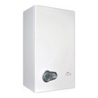
Covers system presentation, supplied components, user interface, and accessories.

3. TECHNICAL DATA AND PERFORMANCE

Heat Pump Technical Data

Provides detailed performance specifications for the heat pump.

ERP Data and Operational Limits

Presents ERP data and operational limits for the heat pump.

Boiler Technical Data

Specifies technical data related to the boiler component.

1. SAFETY PRECAUTIONS

Meanings of Danger, Warning, Caution and Note Symbols

Explains the different hazard and information symbols used in the manual.

1.1 Special Requirements for R32 Refrigerant

1.2 Information Servicing

Servicing Procedures and Checks

Details servicing procedures, work areas, and checks for refrigerating equipment.

1.2 Information Servicing

Repairs to Sealed Components

Instructions for performing repairs on sealed refrigeration system components.

Refrigerant Leak Detection and Removal

Instructions for detecting flammable refrigerants and removing/evacuating them.

2. GENERAL FEATURES

System Overview, Components, and Interface

Covers system presentation, components, user interface, and accessories.

3. TECHNICAL DATA AND PERFORMANCE

3.1 Heat Pump Technical Data

Provides detailed performance specifications for the heat pump.

3.2 ERP Data

3.3 Heat Pump Operational Limits

3.4 Boiler Technical Data

3.4.1 Table for Boiler Technical Data

Presents technical data for the boiler in a tabular format.

3.4.2 Boiler ErP Product Data Sheet

3.5 Available Pressure

3.5.1 Heat Pump Circulator + Boiler Circulator

Pressure curves for combined heat pump and boiler circulator.

3.5.2 Heat Pump Circulator

Pressure curves for the heat pump circulator.

3.5.3 Boiler Circulator

Pressure curves for the boiler circulator.

4. DIMENSIONAL AND PHYSICAL DATA

5. GENERAL VIEW AND INTERNAL UNIT FUNCTIONAL DIAGRAM

5.1 General View

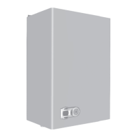
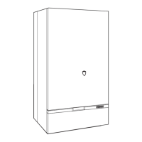
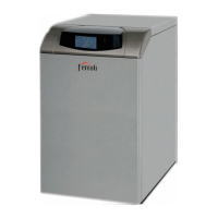
Presents an overall view of the unit's components.

5.2 Indoor Unit Functional Diagram

Shows the functional diagram of the indoor unit's hydraulic system.

6. EXAMPLE OF SYSTEM LAYOUT

7. INSTALLATION

7.1 Inspections on Arrival

Procedures for checking the unit upon delivery.

7.2 Minimum Plant Water Content and Requirements for DHW Boiler

7.3 Limits to the Length and Height Difference of Refrigerant Pipes

7.4 Refrigerant Connections

7.4.1 Airtight Test and Leakage Detection

7.4.2 Air Purge with Vacuum Pump

7.4.3 Heat Insulation

7.4.4 Refrigerant Amount to be Added

7.5 Hydraulic Connections

7.5.3 Water Filter

Instructions for installing and maintaining the water filter.

7.5.4 Tips for a Successful Installation

Recommendations for a correct hydraulic plant installation.

7.5 Hydraulic Connections

7.5.5 Filling with Water

Procedure for filling the hydraulic system with water.

7.5.6 Water Circuit Anti-Freeze Protection

Details the system's anti-freeze protection measures.

7.5.7 Water Piping Insulation

Guidelines for insulating water pipes to prevent condensation and heat loss.

7.6 Boiler Gas Connection

7.7 Boiler Fume Ducts

7.7.1 Warnings

Important warnings regarding boiler fume duct installation.

7.7.2 Connection with Coaxial Pipes

Instructions for connecting the fume system using coaxial pipes.

7.7.3 Connection with Separate Pipes

7.7.4 Use of Flexible Hose Pipe Ø50 and Ø60

7.7.5 Connection to Collective Chimneys

7.8 Connection to Boiler Condensate Discharge

7.9 Electrical Connections

7.9.1 Electrical Data

Provides electrical specifications and connection details.

7.9.1 Opening the Front Panel

7.9.2 User Terminal Block Connections

7.9.2 Connection of System Add-ons

7.9.3 How to Access the Heat Pump Hydronic Board

7.9.4 Heat Pump Hydronic Board

7.9.5 Connections to the Heat Pump Board

EVU-SG Digital Inputs for Photovoltaic Input and Smart Grid

Additional Temperature Probes

8. USER INTERFACE

8.1 Key Function Description

Describes the function of each key on the user interface.

8.2 Meaning of Display Icons

Explains the various icons displayed on the unit's interface.

8.3 Switching DHW and System On and Off

8.4 DHW and System Set Point Configuration

DHW Set Point (min 30°C, max 60°C)

Procedure to set the domestic hot water temperature.

Single Zone Set Point

Procedure to set the temperature for a single system zone.

Zone Z1 Set Point

Procedure to set the temperature for Zone 1.

Zone Z2 Set Point

Procedure to set the temperature for Zone 2.

9. GENERAL USER MENU

9.1 System Menu

Menu for configuring system-level preferences.

9.2 Boiler Menu

Menu for accessing and configuring boiler settings.

9.2.2 Boiler Service Menu

9.3 Heat Pump Menu

9.3.1 User Heat Pump Menu (hp menu)

User-accessible settings for the heat pump operation.

9.3.1 User Heat Pump Menu (hp menu)

DHW and System Settings

Manages DHW functions, silent mode, holiday mode, errors, parameters, and display settings.

9.3.2 Heat Pump Service Menu

DHW and Cooling Mode Parameters

Configuration of DHW modes, priority, pumps, and cooling parameters.

Heating Mode and System Parameters

Configuration of heating modes, temperature settings, and system parameters.

Test Run and Input Definitions

Procedures for test runs, power limitation, and input definitions.

10. SETTINGS TO ENTER BEFORE STARTING UP

10.1 Dip Switch Setting on Indoor Unit Hydronic Board

Configuration of dip switches on the indoor unit's hydronic board.

10.2 Dip Switch Setting of Outdoor Unit Cooling Circuit Board

10.3 Climatic Curves

10.3.1 Temperature Curves for Heating Mode and ECO Heating Mode

Defines temperature curves for heating and ECO modes.

10.3.1 Temperature Curves for Heating Mode and ECO Heating Mode

Climatic Curve 9 in Heating Mode Settable by the User

Allows user customization of climatic curve 9 for heating.

10.3.2 Temperature Curves for Cooling Mode

Climatic Curve 9 in Cooling Mode Settable by the User

Allows user customization of climatic curve 9 for cooling.

11. COMMISSIONING

11.1 Heat Pump Commissioning

Steps for commissioning the heat pump component.

11.2 Commissioning the Boiler

Steps for commissioning the boiler component.

11.2.3 Successive Boiler Switch-ons

11.2.4 Transformation of Boiler Gas Feed

11.2.5 Checking the Boiler Combustion Values

Boiler Calibration Procedure [AUTO SETUP]

Steps for calibrating the boiler using the AUTO SETUP function.

11.2.6 Boiler Test Mode [Test]

11.3 Final Check Before Turning on the Unit

11.4 Turn on the Unit

11.5 System Delivery Water Setpoint Setting

11.5.1 Heating Mode

Setting the water temperature setpoint for heating mode.

11.5.2 Cooling Mode

11.6 Setting DHW Temperature Production

12. TROUBLESHOOTING

LCD Display Off and General Guidelines

Troubleshooting for display issues and general diagnostic procedures.

General Symptoms and Causes

Common symptoms, their causes, and initial corrective actions.

12.2 General Symptoms

Specific Symptom Troubleshooting

Detailed troubleshooting for specific symptoms like pressure relief valve issues or mode transition problems.

12.3 Heat Pump Error Codes

12.4 Boiler Fault Codes

13. MAINTENANCE

Electrical Cabinet Inspection

Inspection and maintenance of the unit's electrical cabinet.

13.1 Access to Internal Components

13.2 Water Load and System Hydraulic Pressure Adjustment

13.3 Periodic Maintenance of the Heat Pump

Component Checks

Covers visual inspection, hydraulic, electrical, fan, exchanger, and filter checks.

13.4 Unscheduled Maintenance and Replacement of Heat Pump Components

13.4.1 Heat Pump Circulator

Steps for replacing the heat pump circulator.

13.5 Periodic Boiler Maintenance

13.6 Unscheduled Maintenance and Replacement of Boiler Components

13.6.1 Replacement of the Boiler Gas Valve

Steps for replacing the boiler's gas valve.

13.6.2 Replacement of the Boiler Main Heat Exchanger

13.6.3 Replacement of the Boiler Electronic Board

13.6.4 Replacement of Boiler Fan

13.6.5 Replacement of Boiler Pressure Transducer

14. WIRING DIAGRAM

15. REFRIGERANT DIAGRAM

Related product manuals