12
EN
cod. 3540I815 - 07/2011 (Rev. 00)
2.4 Adjustments
Setting the clock (methods B and C only)
1. Press the day/time setting button (detail 1 - fig. 1).
2. The CLOCK and DAY icons flash on the display (detail 7 - fig. 1): set the current day
of the week with the + and - buttons (details 4 and 6 - fig. 1), considering that 1=Mon-
day, 7=Sunday. Confirm the day by pressing the day/time setting button (detail 1 -
fig. 1).
3. The two digits of the CURRENT HOUR and the CLOCK icon flash on the display
(detail 7 - fig. 1): set the exact hour with the + and - buttons (details 4 and 6 - fig. 1),
from 00 to 23. Confirm the hour by pressing the day/time setting button (detail 1 1 -
fig. 1).
4. The two digits of the CURRENT MINUTES and the CLOCK icon flash on the display
(detail 7 - fig. 1): set the exact minutes with the + and - buttons (details 4 and 6 -
fig. 1), from 00 to 59. Confirm the minutes by pressing the day/time setting button
(detail 1 - fig. 1). Automatic Heating, Manual On, Manual Off mode
Press the operation mode selection button (detail 2 - fig. 1) to set the:
1. In Automatic mode, the display (detail 7 - fig. 1) shows the CLOCK icon. The burner
activation and deactivation request depends on the set weekly programme. In the
request time band, the display (detail 7 - fig. 1) also shows the ON icon.
2. In Manual On mode, the display (detail 7 - fig. 1) only shows the ON icon. The burner
is always in request status.
A
The set weekly programme is bypassed.
3. In Manual Off mode, the display (detail 7 - fig. 1) does not show the ON icon or the
CLOCK icon. The burner is off.
A
The set weekly programme is bypassed.
Preset weekly programme
The weekly programme is preset with 3 ON time bands and 3 OFF time bands; equal for
every day of the week. In the request time band, the display (detail 7 - fig. 1) shows the
ON icon.
A
Attention: Check burner operation methods (see sec. 4.1)
Modifying the weekly programme (methods B and C only)
1. Press the Programming button "P" (detail 5 - fig. 1)
2. Select the day to be programmed with the + and - buttons (details 4 and 6 - fig. 1):
• Day 1 and Radiator flashing: Monday heating programming
• Day 2 and Radiator flashing: Tuesday heating programming
• Day 3 and Radiator flashing: Wednesday heating programming
• Day 4 and Radiator flashing: Thursday heating programming
• Day 5 and Radiator flashing: Friday heating programming
• Day 6 and Radiator flashing: Saturday heating programming
• Day 7 and Radiator flashing: Sunday heating programming
• Day 15 and Radiator flashing: Monday - Friday heating programming
• Day 67 and Radiator flashing: Saturday - Sunday heating programming
• Day 16 and Radiator flashing: Monday - Saturday heating programming
• Day 17 and Radiator flashing: Monday - Sunday heating programming
• Day 15 and Radiator flashing: not used
3. Press the Programming button "P" (detail 5 - fig. 1):
4. 06:30 and Radiator flashing, ON, 1
• Use the + and - buttons (details 4 and 6 fig. 1) to modify the start of the 1st ON
time band; e.g. 06:00Press the Programming button "P" (detail 5 - fig. 1)
5. 08:30 and Radiator flashing, 2
• Use the + and - buttons (details 4 and 6 fig. 1) to modify the start of the 1st OFF
time band; e.g. 09:00Press the Programming button "P" (detail 5 - fig. 1)
6. 12:00 and Radiator flashing, ON, 3
• Use the + and - buttons (details 4 and 6 fig. 1) to modify the start of the 2nd ON
time band; e.g. 12:30Press the Programming button "P" (detail 5 - fig. 1)
7. 12:00 and Radiator flashing, 4
• Use the + and - buttons (details 4 and 6 fig. 1) to modify the start of the 2nd OFF
time band; e.g. 14:00Press the Programming button "P" (detail 5 - fig. 1)
8. 16:30 and Radiator flashing, ON, 5
• Use the + and - buttons (details 4 and 6 fig. 1) to modify the start of the 3rd ON
time band; e.g. 16:00Press the Programming button "P" (detail 5 - fig. 1)
9. 22:30 and Radiator flashing, 6
• Use the + and - buttons (details 4 and 6 fig. 1) to modify the start of the 3rd OFF
time band; e.g. 23:30Press the Programming button "P" (detail 5 - fig. 1)
10. By repeating the above procedure it is possible to programme the 4th ON time band
and the 4th OFF time band.
11. Press the Programming button "P" (detail 5 - fig. 1) for 3 seconds to exit the pro-
gramming mode.
Parameters menu
Press the programming button “M” (detail 2 - fig. 1) for 5 seconds to access the param-
eters menu. Parameter “u01”, identified by the message SET 01, is displayed. Press the
button "P" (detail 5 - fig. 1) to scroll the list of parameters.
To modify the value of a parameter, press the + and - buttons (details 4 and 6 - fig. 1):
the change will be automatically saved. After modifying the parameter, it is necessary to
wait 3 seconds: the datum item flashes and is saved.
Table. 1
Press the "operation mode selection - M" button (detail 2 – fig. 1) for 5 seconds to exit
the menu.
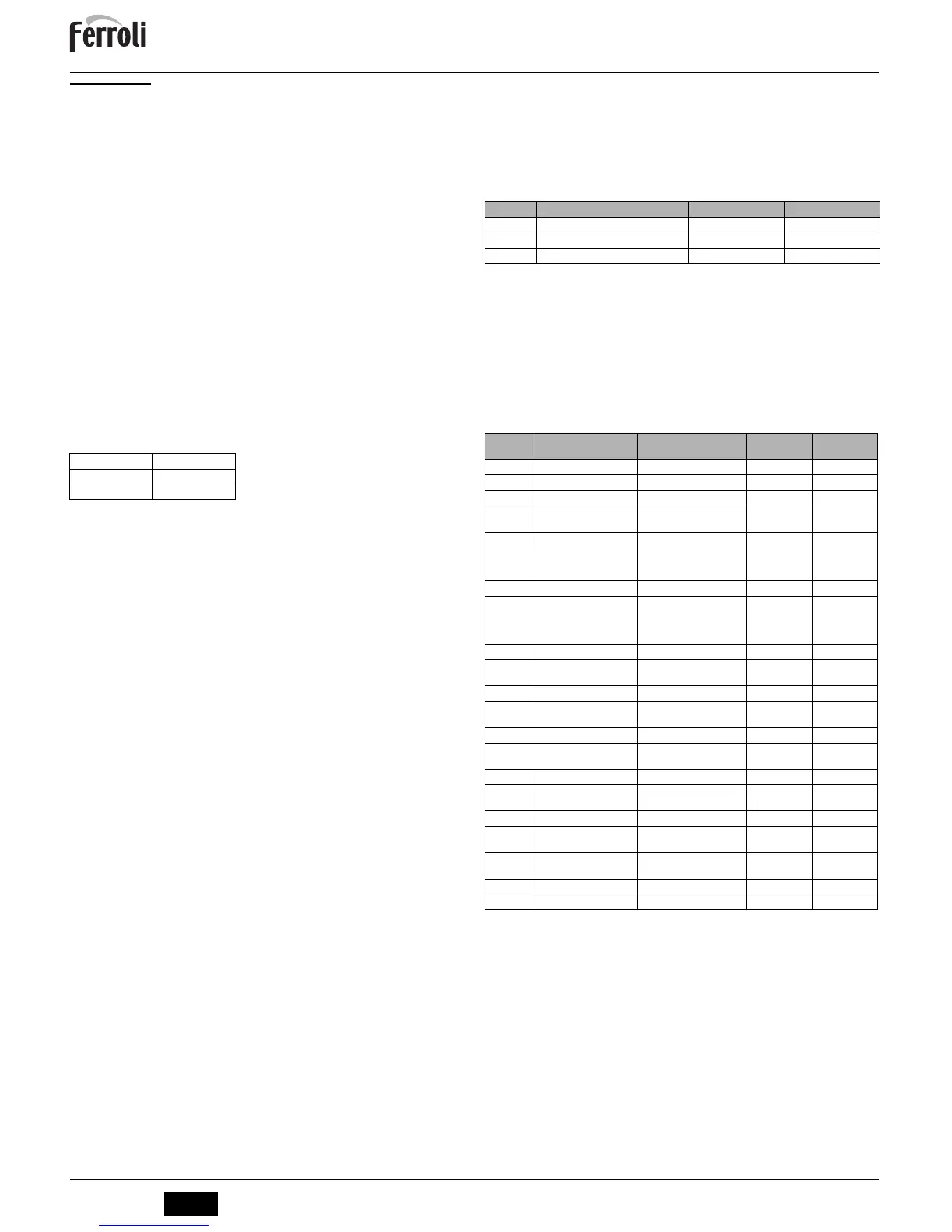
Service parameters menu
Press the programming button “P” (detail 5 - fig. 1) for 10 seconds to access the param-
eters menu. Parameter “t01”, identified by the message SET 01, is displayed. Press the
button "P" (detail 5 - fig. 1) to scroll the list of parameters.
To modify the value of a parameter, press the + and - buttons (details 4 and 6 – fig. 1):
the change will be automatically saved. After modifying the parameter, it is necessary to
wait 3 seconds: the datum item flashes and is saved.
Table. 2
Press the programming button “P” (detail 5 - fig. 1) for 10 seconds to exit the menu.
06:30 08:30
12:00 12:00
16:30 22:30
Parameters Description Range SUN P7 - P12
u01 Delivery setpoint adjustment 30 - 80°C 80°C
u02 Burner max. power 1 - 5 3
u03 Burner operation methods (see par. 3.1) 0 - 2 0
Parameters Description Range Default
/
SUN P7
SUN P12
t01 Pellet loading function 0=Disabled 1=Enabled 0=Disabled 0=Disabled
t02 Delivery probe 0=Disabled 1=Enabled 1=Enabled 1=Enabled
t03 Fan setpoint in Lighting 0-200 Pa 51 Pa 51 Pa
t04 Auger activation time in
Lighting
0-100 (1=4 seconds) 8 8
t05 Adjustment calculation timer
(Only with Modulating burner
operation with delivery
Probe)
0-100 seconds 5 seconds 5 seconds
t06 Ramp function timer 0-100 seconds 100 seconds 100 seconds
t07 Period (activation+deactiva-
tion time) with auger operat-
ing (from Power 1 to Power
5)
0-50 seconds 15 seconds 12 seconds
t08 Fan setpoint at Power 1 0-200 Pa 51 Pa 51 Pa
t09 Auger activation time at
Power 1
0-100 (100=10 seconds) 28 38
t10 Fan setpoint at Power 2 0-200 Pa 74 Pa 70 Pa
t11 Auger activation time at
Power 2
0-100 (100=10 seconds) 38 40
t12 Fan setpoint at Power 3 0-200 Pa 120 Pa 100 Pa
t13 Auger activation time at
Power 3
0-100 (100=10 seconds) 46 45
t14 Fan setpoint at Power 4 0-200 Pa 150 Pa 120 Pa
t15 Auger activation time at
Power 4
0-100 (100=10 seconds) 53 60
t16 Fan setpoint at Power 5 0-200 Pa 170 Pa 155 Pa
t17 Auger activation time at
Power 5
0-100 (100=10 seconds) 56 65
t18 Burner operation selection
(Only with Delivery Probe)
0=On/Off 1=Modulating 0=On/Off 0=On/Off
t19 Post-Ventilation time 2 0-100 (100=10 seconds) 99 99
t20 Photoresistance voltage 00-30 (50 = 5Vdc) -- --


 To Next Page
 Loading...