T-ONE C HE
16 EN
cod. 3541D730 - Rev. 00 - 05/2013
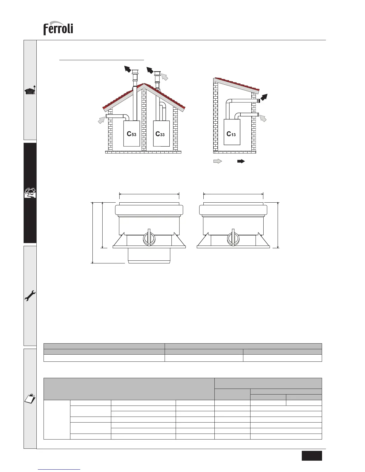
Connection with separate pipes
fig. 22 - Examples of connection with separate pipes ( = Air / = Fumes)
For the connection of separate ducts, fit the unit with the following starting accessory:
fig. 23 - Starting accessory for separate ducts
Before proceeding with installation make sure the maximum permissible length has not been exceeded, by means of a
simple calculation:
1. Completely establish the layout of the system of split flues, including accessories and outlet terminals.
2. Consult the table 3 and identify the losses in m
eq
(equivalent metres) of every component, according to the instal-
lation position.
3. Check that the sum total of losses is less than or equal to the maximum permissible length in table 2.
Table. 2 - Max. length separate ducts
Table. 3 - Accessories
Separate ducts
T-ONE 25C HE T-ONE 30C HE
Max. permissible length 80 m
eq
70 m
eq
Losses in m
eq
Air
inlet
Fume exhaust
Vertical Horizontal
Ø 80 PIPE 1 m M/F 1.0 1.6 2.0
BEND 45° M/F 1.2 1.8
90° M/F 1.5 2.0
PIPE SECTION with test point 0.3 0.3
TERMINAL air, wall 2.0 -
fumes, wall with antiwind - 5.0
FLUE Split air/fumes 80/80 - 12.0