T-ONE C HE
24 EN
cod. 3541D730 - Rev. 00 - 05/2013
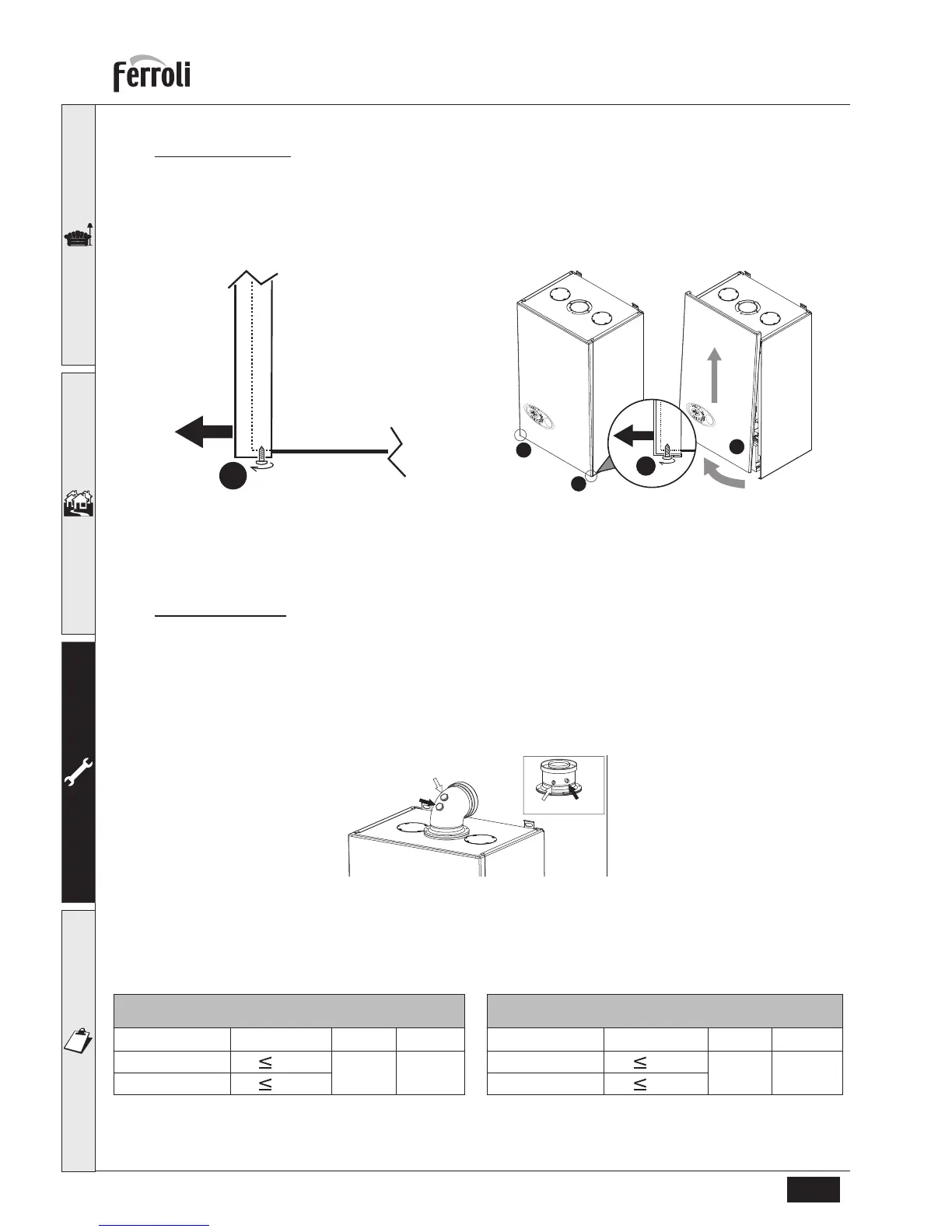
Opening the casing
To open the boiler casing, you need to follow the sequence given below and the instructions of fig. 31.
1. Using a screwdriver, partially unscrew the 2 screws “A” (fig. 30)
2. Lift the panel “B”
B
Before carrying out any operation inside the boiler, disconnect the electrical power supply and close the gas
cock upstream
fig. 30
fig. 31 - Opening the casing
B
When remounting the panel “B” check carefully it is correctly mounted.
Combustion check
Connect the flue gas analyzer to the flue gas sampling point as shown in the fig. 32 and check combustion as described
in table 4 and table 5.
1. Press the CH button for 5 seconds to place boiler into test mode
2. Wait for 10 minutes for the boiler to stabilize fully
3. Take the measurement and record
4. Take the boiler to minimum output by pressing the CH – button, allow the boiler to stabilize for a further 10 minutes.
5. Take the measurement and record.
fig. 32 - Flue gas sampling Point
1 = Air - 2 = Fumes
Tabella. 4 - Maximum rate Tabella. 5 - Minimum rate
If the combustion reading is greater than the acceptable value AND the integrity of the complete flue system
and combustion circuit seals have been verified and the inlet gas pressure (and gas rate) have been verified,
proceed as in section Setting the Air/Gas Ratio valve.
NATURAL GAS ACCEPTABLE COMBUSTION RANGE
MAXIMUM RATE AFTER 10 MINUTES FROM COLD
Boiler Model
CO/CO
2
RATIO CO
2
NG CO
2
LPG
T-ONE 25C HE
0.004
8,7 ÷ 9,2 10 ÷ 10,5
T-ONE 30C HE
0.004
NATURAL GAS ACCEPTABLE COMBUSTION RANGE
MINIMUM RATE AFTER 10 MINUTES FROM COLD
Boiler Model CO/CO
2
RATIO CO
2
NG CO
2
LPG
T-ONE 25C HE
0.004
8,2 ÷ 8,7 9,5 ÷ 10,0
T-ONE 30C HE
0.004
 Loading...