Do you have a question about the Festo CMMT-AS Series and is the answer not in the manual?
Identifies the intended audience for this document, including those who mount, operate, and plan the product.
Lists related documents and standards crucial for understanding the safety sub-functions (STO, SBC).
Specifies the particular version of the Servo drive CMMT-AS-...-S1 this documentation refers to.
Refers to product labelling information found within the Manual Assembly, Installation section.
Lists the key industry standards that the product complies with for safety and performance.
Provides critical instructions for safe operation, installation, and assessment of the product's suitability.
Defines the proper and intended applications for the safety sub-functions STO, SBC, and SS1.
Details the specific applications for which the stated safety reference values are sufficient.
Specifies components that are permitted for use with the safety functions, adhering to standards.
Outlines potential misuse scenarios and conditions to avoid for safe operation of the servo drive.
Stresses the necessity of qualified personnel for installation, operation, and work on safety-related systems.
Indicates the product's conformity with relevant EU directives, including EMC and Machinery directives.
Discusses the product's status as a safety device and its compliance with relevant standards.
Describes the safety-related performance features of the servo drive CMMT-AS, including STO, SBC, and SS1.
Details the Safe Torque Off function, its principle, and application according to EN 61800-5-2.
Explains how the Safe Torque Off (STO) function is activated via control inputs.
Illustrates the internal working and circuitry of the STO safety function.
Describes how the STO status is communicated back to the safety relay unit via the STA diagnostic output.
Details the timing diagrams and parameters associated with the STO function's operation.
Explains the Safe Brake Control (SBC) function, its purpose, and application for holding brakes.
Describes the purpose and usage scenarios for the Safe Brake Control function.
Illustrates the internal working and circuitry of the SBC safety function.
Explains how the Safe Brake Control (SBC) function is activated via control inputs.
Describes how SBC status is communicated back to the safety relay unit via the SBA diagnostic output.
Outlines procedures and tables for testing the SBC function's operation and feedback.
Explains how to interpret the SBA feedback signal for evaluating the SBC function's status.
Details the timing diagrams and parameters associated with the SBC function's operation.
Lists requirements and considerations for using brakes with the SBC function.
Discusses the necessity and procedure for performing brake tests, referencing DGUV information.
Details the Safe Stop 1 (SS1) function, its principle, and application according to EN 61800-5-2.
Lists the prerequisites for implementing the SS1 function, including wiring and timing.
Explains the operational steps and use cases for the Safe Stop 1 function.
Describes the necessary logic circuits required in the safety relay unit for the SS1 function.
Explains how the SS1 function status is reported, potentially using the STA signal.
Details the timing diagrams and parameters associated with the SS1 function's operation.
Explains how to connect multiple servo drives in a ring configuration for safety functions.
Provides a practical wiring example for cross-connecting diagnostic outputs like STA.
Discusses measures to prevent wiring faults and ensure reliable operation of safety functions.
Lists requirements and examples of suitable safety relay units for implementing safety functions.
Describes the Power Drive System (PDS) interfaces to the external world, including power and signals.
Details the specific interfaces of the Power Drive System (PDS) for external connections.
Highlights safety precautions and warnings during the installation process of the servo drive.
Details the wiring and setup procedures for the Safe Torque Off (STO) function.
Lists the specific digital inputs and diagnostic outputs required for STO configuration.
Provides a practical wiring example illustrating the connection of the STO safety function.
Explains the sample circuit diagram provided for the STO safety function setup.
Details the wiring and setup procedures for the Safe Brake Control (SBC) function.
Lists the specific digital inputs and diagnostic outputs required for SBC configuration.
Provides a practical wiring example illustrating the connection of the SBC safety function.
Explains the sample circuit diagram provided for the SBC safety function setup.
Details the wiring and setup procedures for the Safe Stop 1 (SS1) function.
Lists the specific digital inputs and diagnostic outputs required for SS1 configuration.
Provides a practical wiring example illustrating the connection of the SS1 safety function.
Instructions for installing the drive for operation without any safety functions enabled.
Specifies the minimal wiring required when operating the drive without safety functions.
Safety precautions to be observed during the commissioning phase of the servo drive.
Guidance on preparing and utilizing the safety functions (STO, SBC) during commissioning.
Provides checklists to help validate the safety functions after installation and modifications.
Example questions based on EN 12100 for validating the safety of the system.
Example questions based on EN ISO 13849-2 for validating the safety of the system.
Explains how to interpret LED indicators on the device for diagnosing malfunctions and safety status.
Describes the meaning of the safety LED status indicators, including error and active states.
Information on product repair and replacement procedures, emphasizing replacement over repair.
Specific technical data related to safety engineering, including certifications and reference data.
Details about safety certifications, testing bodies, and EC-type examination certificates.
Key safety parameters and reference data, including request rate and reaction times.
Specific safety performance data for the STO function, covering SIL, PL, and failure probabilities.
Specific safety performance data for the SBC function, covering SIL, PL, and failure probabilities.
Further safety performance data for the SBC function, including common cause factors and availability.
Provides general technical specifications and product conformity details like CE marking.
Information on CE marking, EU EMC Directive, Machinery Directive, and RoHS Directive compliance.
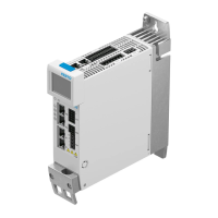
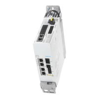
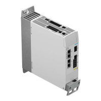
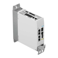
Basic technical specifications of the CMMT-AS, including type, mounting, and weight.
Specifies environmental conditions such as temperature and humidity during transport.
Specifies environmental conditions such as temperature and humidity during storage.
Specifies environmental conditions such as temperature and humidity during operation.
Information on the expected service life of the device under different load conditions.
Provides detailed electrical specifications for the servo drive and its connections.
Technical details and specifications for the motor auxiliary connection at X6B.
Specifications for the holding brake output, including design, electrical data, and error detection.
Details on digital inputs, outputs, and the ready contact at connection X1A.
Defines the voltage and current ranges for digital inputs, including ON, OFF, and transition ranges.
Specific parameters and tolerances for the STO control inputs.
Specific parameters and tolerances for the SBC control inputs.
Specifications for the diagnostic outputs STA and SBA, including voltage and current ranges.
Details on the inputs and outputs available at connection X1C for axis control.
Specifications for the BR-EXT output, including design, voltage range, and protective functions.
Further specifications for the BR-EXT output, including fault detection and load characteristics.
| Product Type | Servo Drive |
|---|---|
| Series | CMMT-AS |
| Mounting Position | Any |
| Communication Interfaces | EtherCAT, CANopen |
| Feedback System | Incremental encoder, Absolute encoder |
| Protection Class | IP20 |
| Nominal Voltage Range DC | 24 V DC |
| Rated Output | Varies by model |
| Power Range | 0.1 - 7.5 kW |
| Max. Output Current | Varies by model |
| Output Current | Varies by model |
| Control Modes | Position, Torque |
| Operating Temperature | 0°C to +55°C |
| Storage Temperature | -25 to 70 °C |
| Relative Humidity | 5% to 85% non-condensing |
| Vibration Resistance | 3M2 according to EN 60721-3-3 |
| Shock Resistance | According to EN 60068-2-27 |
| Input Voltage | DC |