Do you have a question about the Festo CMMT-ST-SW and is the answer not in the manual?
Lists all available documents for the product and user documentation.
Specifies the CMMT-ST servo drive and plug-in versions, and firmware package versions.
Provides safety instructions for commissioning and operation, emphasizing checking control functions and potential hazards.
Explains the conventions used in the document, such as hexadecimal values and marking of parameters.
Introduces the CMMT-ST plug-in, its integration into Festo Automation Suite, and its functions.
Describes the interface of the CMMT-ST plug-in, including contexts, toolbar, and working area.
Explains how to open the plug-in, connect to the device, and synchronize data between plug-in and device.
Details the interface for parameterisation, graphical and tabular displays, and how to enter parameters.
Covers the interface for diagnosis, device state, I/O state, error log, error classification, and trace configuration.
Explains the interface for control, manual movement, and record list operations.
Describes how to connect and integrate a device into a Festo controller, including operating modes.
Discusses controller communication interfaces, IP address settings, MAC addresses, and firmware management.
Details IP address configuration, factory settings, Ethernet interface capabilities, and MAC addresses.
Explains firmware management, compatibility checks, and firmware download procedures.
Covers default, factory, user, and project parameter sets, and their behaviour during online connection.
Explains master control, determining the interface for motion commands, and how it can be transferred.
Details device services executed by methods, such as reset device, and return values for method status and return codes.
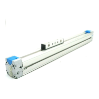
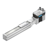
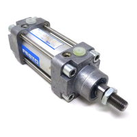
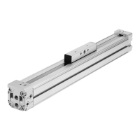
Guides through selecting and configuring drive components like servo controller, motor, axis, and mounting kit.
Explains how to configure motors, including importing data, and parameters for motor cable and encoders.
Covers encoder parameters, configuration of encoder 1 (incremental and BiSS-C), and selection of position control encoder.
Details parameterisation of gear units, transmission factors, and gear ratio configuration.
Explains parameterisation of digital inputs and outputs, general settings, and configuration for X1A and X1C connectors.
Covers protective functions for the device, including I²t monitoring and temperature monitoring.
Describes the protective function to prevent thermal damage to the power output stage by monitoring limit values.
Explains the simplified thermal motor model used for protecting the connected motor from thermal overload.
Details the protective function for monitoring power module temperature against overtemperature, including warning and upper/lower limits.
Covers the protective function that monitors the internal system for errors, switching off the power output stage if an error is detected.
Explains mains voltage monitoring and DC link voltage monitoring to protect against failures and voltage variations.
Defines how the device changes operating statuses and the internal finite state machine.
Describes the internal finite state machine that defines how operating statuses change, including transitions between states.
Lists and describes the different operating modes for performing motion commands: Profile and Cyclic Synchronised.
Explains the positioning profile position operating mode, path curve calculation, and supported position specifications.
Details the velocity mode profile, trajectory calculation based on motion quantities, and supported velocity settings.
Describes the force/torque mode, setpoint curve calculation, and supported variants including holding brake.
Explains the mode enabling pre-set command values in a fixed time grid, synchronized with the higher-order controller.
Covers cyclic synchronised velocity mode, enabling pre-set command values via drive profile (SYNC interval) for synchronized operation.
Details cyclic synchronised force/torque mode, enabling pre-set command values via drive profile (SYNC interval) for synchronized operation.
Explains the stop command, which aborts the current motion command, with subsequent reactions depending on the trigger.
Describes the reactions to the hold command, which depends on the active operating mode and can abort or continue the current command.
Explains the process of homing the drive to approach an absolute, unique position.
Details saving command records in a record table, addressing them by number, and activating them as foreground or background processes.
Explains how sequencing multiple records enables specification of command sequences, executed after starting with no further start commands.
Describes the event table for monitoring events parallel to step enabling conditions, branching to a record if an event occurs.
Explains how the drive can move to any position in jog mode until the command for jogging is pending.
Details motion monitoring functions that monitor the drive system and protect drive components from damage.
Explains the function indicating if the target value has been reached, monitoring various target values simultaneously.
Describes the monitoring of the difference between setpoint and actual values for position and speed.
Covers monitoring the drive's movement after reaching the target window, depending on operating mode (position, speed, or torque).
Explains how hardware limit switches limit the positioning area and how the drive must be positioned between limit positions.
Details how software limit positions control the traversing range and are related to the axis zero point.
Indicates when the drive is not moving or moving minimally below a threshold value, preventing drifting.
Explains the monitoring function combining standstill and current monitoring to check if specified limits are reached.
Describes the monitoring function for stroke limits, applicable to speed and power operation, contrasting with software limit position monitoring.
Details the monitoring function to detect excessive speeds and prevent drive spinning by stopping.
Covers monitoring drive movement as a function of specified effective direction of torque, allowing reverse movement below velocity threshold.
Indicates when the remaining path during ongoing positioning command is below the specified limit value.
Explains the monitoring function indicating when a trajectory (movement) has been completed.
Indicates when the reference switch is activated, monitoring its status and configuration.
Describes the function that blocks drive movement in one or both directions, triggered automatically by exceeding software limits or hardware switches.
Explains the cascade controller's basic structure consisting of position, velocity, and current regulators.
Details the P-controller design for calculating velocity specifications from control difference and the use of dead zone members.
Describes the PI controller for calculating torque specifications and its interaction with current regulators.
Explains the current regulator comprising active and reactive current regulators for secondary power output stages.
Covers active, and 3 additional control parameter sets for parameterisation, including inertia and filter time constants.
Discusses limitations on setpoint specifications for the trajectory generator, affected by active set table or profile mode.
Explains how application limitations define setpoint specifications, comparing movement variables with limitations.
Details the cascade controller's limitations for velocity and torque setpoints, composed of static and dynamic data.
Explains how torque limitation limits torque related to the drive output shaft, converting user specifications to resulting torque.
Describes pilot control creating setpoint values for the cascade controller, improving positioning behavior and reducing errors.
Explains the use of internal notch filters to suppress oscillations and filter interfering frequencies from the active current.
Covers using auto tuning to determine control parameters for position and velocity controllers based on measurements.
Describes the cam controller generating trigger signals at parameterised positions, usable for position switch simulation.
Explains how the device detects current positions during command processing using trigger signals at CAP input.
Details actuation with constant currents, suitable for low speeds, and possible with or without an encoder.
Explains field weakening for synchronous motors to reach higher rotational speeds by reducing negative field voltage.
Describes continuous monitoring of feedback signals for STO safety sub-function, triggering messages and fault responses.
Outlines comprehensive diagnostics options via LEDs, commissioning software, web server, and fieldbus.
Explains how devices issue messages and react based on parameterised severity of diagnostic events.
Details how the device determines diagnostic status from active messages, represented as a bit mask.
Lists possible statuses for messages: Active, Cancelled, and Acknowledged.
Explains the meaning of message statuses (Active, Cancelled, Acknowledged) and how messages remain active or are cancelled/acknowledged.
Describes the uniform design of messages including ID, name, status, classification, and time stamp.
Explains how messages are stored in a volatile directory, sorted by severity and time, accessed via plug-in.
Describes the non-volatile ring memory for storing messages traceable at a later date, with FIFO principle.
Outlines how acknowledging messages changes their status and how errors are handled.
Provides a reference list for diagnostic messages, including ID, message, description, remedy, classification, and error memory.
Details the process of recording all device data in the parameter directory, including selecting values, sampling interval, and trigger configuration.