Do you have a question about the Festo EMCA-EC-67 CO Series and is the answer not in the manual?
Provides essential safety guidelines for handling and operation.
Warns about burns from hot surfaces and necessary precautions.
Defines the specific applications and limitations for product use.
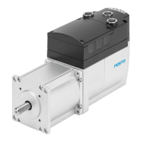
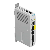
Describes the main components and general characteristics of the integrated drive.
Describes the integrated web server for device status and configuration access.
Lists and briefly describes the supported drive functions.
Explains the homing process to determine the reference point and axis zero point.
Details various methods for performing the homing sequence.
Details the homing procedure that uses a mechanical stop.
Lists and describes parameters that influence the homing process.
Details manual drive control using jog mode via FHPP or FCT.
Describes capturing current positions as teaching points via FHPP or FCT.
Explains how the drive reaches a target position via a calculated path.
Details how the drive regulates velocity or rotational speed.
Explains how the drive controls force or torque by regulating motor current.
Details the functions of stop (halt) and quick-stop deceleration.
Explains the function, operation, and parameterisation of the holding brake.
Explains how to switch between stored motion records based on start conditions.
Lists internal sensors and functions that ensure operational reliability.
Describes how diagnostic messages are classified and how errors are managed.
Explains the Ethernet interface for device configuration and diagnostics.
Covers critical safety warnings for electrical shock and unexpected movement.
Details the pin allocation for the Safe Torque Off (STO) interface.
Presents safety warnings and general notes before starting commissioning.
Introduces the Festo Configuration Tool for commissioning the drive.
Details how to establish an Ethernet connection for device configuration.
Outlines the sequence of operations for initial drive setup and configuration.
Emphasizes precise configuration and parameterization using FCT.
Provides recommendations for performing the homing procedure.
Explains how to save and load device parameter files using FCT or web server.
Explains methods to access and retrieve diagnostic information from the device.
Lists diagnostic messages and their corresponding fault clearance procedures.
Continues the list of diagnostic messages and fault clearance steps.
Continues the list of diagnostic messages and fault clearance steps.
Continues the list of diagnostic messages and fault clearance steps.
Continues the list of diagnostic messages and fault clearance steps.
Continues the list of diagnostic messages and fault clearance steps.
Continues the list of diagnostic messages and fault clearance steps.
Continues the list of diagnostic messages and fault clearance steps.
Continues the list of diagnostic messages and fault clearance steps.
Continues the list of diagnostic messages and fault clearance steps.
Continues the list of diagnostic messages and fault clearance steps.
Continues the list of diagnostic messages and fault clearance steps.
Continues the list of diagnostic messages and fault clearance steps.
Continues the list of diagnostic messages and fault clearance steps.
Continues the list of diagnostic messages and fault clearance steps.
Continues the list of diagnostic messages and fault clearance steps.
Continues the list of diagnostic messages and fault clearance steps.
| Nominal operating voltage DC | 24 V DC |
|---|---|
| Max. output current | 10 A |
| Interfaces | CANopen |
| Communication interface | CANopen |
| Protection class | IP20 |
| Storage temperature | -20 ... +70 °C |