Translation of the original instructions
© 2020 all rights reserved to Festo SE & Co. KG
1 Applicable documents
All available documents for the product èwww.festo.com/pk.
2 Safety
2.1 Safety instructions
– Observe labelling on the product.
– Prior to assembly, installation and maintenance work: Switch off power sup
ply, ensure that it is off and secure it against being switched back on.
– Store the product in a cool, dry, UVprotected and corrosionprotected envir
onment. Ensure that storage times are kept to a minimum.
– Observe tightening torques. Unless otherwise specified, the tolerance
is±20%.
2.2 Intended Use
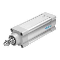
The electric cylinder is intended to be used for positioning payloads in combina
tion with tools or as a drive when external guides are used.
2.3 Training of qualified personnel
Installation, commissioning, maintenance and disassembly should only be con
ducted by qualified personnel. The qualified personnel must be familiar with
installation of electrical control systems.
3 Further information
– Accessories èwww.festo.com/catalogue.
– Spare parts èwww.festo.com/spareparts.
4 Service
Contact your regional Festo contact person if you have technical questions
è www.festo.com.
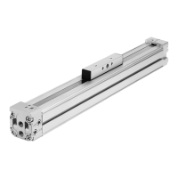
5 Product overview
5.1 Function
The electric cylinder converts the rotary motion of the mounted motor into a linear
motion of the nonrotating piston rod. The lead screw converts the torque of the
motor into a feed force. The linear movement of the piston rod is precisely guided
by the guide in the bearing cap. Sensors enable the monitoring of end positions,
reference position and intermediate position.
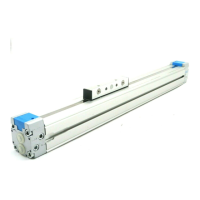
Lead screwESBF-LS Ball screw driveESBF-BS
– Low speeds
– Selfbraking with deenergised motor
(without brake)
– High speeds
– High forces
Tab. 1 Overview of Lead Screw
5.2 Product Design
Product Design ESBF
1
Piston rod
2
Threaded hole for mounting
3
Bearing cap
4
Cylinder profile
5
Pressure compensation opening
6
Drive cover
7
Drive shaft
8
Threaded hole for motor mounting
kit
Fig. 1 Product structure ESBF (example ESBFBS)
6 Transport and Storage
NOTICE!
Unexpected and unbraked movement of components
• Secure moving components for transport.
Transport and Storage Conditions
– Take product weight into account è 14 Technical data.
Weight>25kg: transport with a suitable hoist (crossbrace) or with two per
sons.
– Take the product focus into consideration.
– Store and transport the product in its original packaging.
– Store product in a cool, dry, shaded and corrosion protected environment.
– Store product in ambient conditions without oils, greases and degreasing
vapours.
– Ensure short storage times.
7 Mounting
7.1 Safety
WARNING!
Risk of Injury due to Unexpected Movement of Components
For vertical or slanted mounting position: when power is off, moving parts can
travel or fall uncontrolled into the lower end position.
• Bring moving parts of the product into a safe end position or secure them
against falling.
7.2 Unpacking
1. Open the packaging.
2. Remove all transport materials (e.g.foils, caps, cardboard boxes).
3. Remove the product from the packaging and place it on the mounting surface.
4. Dispose of packaging and transport materials è 13 Disposal.
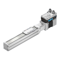
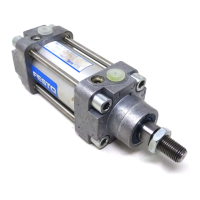
7.3 Mounting the Motor
Lateral Force on the Drive Shaft
When mounting the motor and motor mounting kit, do not exceed the max. lateral
force Fq of the drive shaft (forexample toothed belt tension when mounting the
parallel kit) è 14.2 Characteristic Curves.
Fig. 2 Motor mounting
Requirement
– Only loosen screws or threaded pins that are described in the directions in
the instruction manual.
– Provide sufficient space for connecting the pressure compensation
è Connecting Pressure Compensation (ESBF ... S1 only).
8111672
ESBF-BS, ESBF-LS
Electric cylinder
8111672
201906c
[8111674]
Instructions| Operating
Festo SE & Co. KG
Ruiter Straße 82
73734 Esslingen
Germany
+49 711 3470
www.festo.com