1. Select the motor and motor mounting kit from
Festoèwww.festo.com/catalogue.
When using other motors: observe the critical limits for forces, torques and
velocities.
2. Fasten motor mounting kit, observe instructions èwww.festo.com/sp.
3. Fasten the motor without tension. Support large and heavy motors.
Connect motor cables only on completion of mounting.
7.4 Mounting the Cylinder
High Mechanical Loads on the Mounting Connections
If high rectified torques are applied to the drive system at the same time, this
leads to high mechanical loads at the mounting interfaces.
• The foot mountingHNC, CRHNC should only be used in combination with the
profile mountingEAHF.
• In the case of an inclined or horizontal mounting position with direct mount
ing or flange mountingEAHHV2, the drive system must be additionally sup
ported near the motor mounting.
Requirement
– No collision in the movement space of the attachment component with
mounting and sensor components.
– Sufficient space for reaching and mounting the pressure compensation port.
– Flatness of the mounting surface max. 0.2mm over the stroke length of the
bearing surface.
– No distortion or bending when installing the product.
1. Select mounting attachments èwww.festo.com/catalogue.
2. Place the mounting attachments on the support points.
3. Tighten retaining screws.
Observe max. tightening torque and max. screwin depth.
For additional information, contact your local Festo Service.
Profile mounting
EAHF-V2
Trunnion flange mount-
ing kit DAMT-V1
Direct mounting
Flange mounting
EAHH-V2
Profile Bearing cap
Mounting via profile Mounting via thread Mounting via thread
Tab. 2 Overview of Mounting Components for Bearing Caps and Profile
Swivel flange DAMS,
SNC..., CRSNCS
Trunnion flange ZNCF,
CRZNG
Foot mounting HNC,
CRHNC
Parallel kit
Mounting via thread Mounting via thread Mounting via thread
Tab. 3 Overview of Mounting Components for Parallel Kit
Size 32 40 50 63 80 100
Profile mountingEAHFV2
Screw Instruction manual èwww.festo.com/sp.
Trunnion flange mounting kitDAMTV1
Screw M5 M6 M6 M8 M8 M8
Max. tightening torque [Nm] 4
+1
8
+1
8
+2
18
+2
28
+2
28
+2
Direct mounting
Flange mountingEAHHV2
Foot mountingHNC, CRHNC
Swivel flangeDAMS (not ESBFBF32)
Trunnion flangeZNCF, CRZNG
Screw M6 M6 M8 M8 M10 M10
Max. tightening torque [Nm] 6 6 12 12 25 25
Max. screwin deptht
max
[mm] 16 16 17 17 17 17
Swivel flangeSNC..., CRSNCS
Screw Instruction manual èwww.festo.com/sp.
Tab. 4 Information on Mounting Attachments
7.5 Mounting the Attachment Component
Torque on the Piston Rod
During commissioning and operation, the piston rod may only be operated
without torque.
If external torques occur, an external guide must be used.
Mounting the Attachment Component on the Piston Rod
When attaching the attachment component, do not exceed the max. torque of the
piston rod. The max. torque of the piston rod may only be used for a short time
during mounting è Tab. 7 Information on Attachment Components.
Collision-free Torque-free Centre of gravity
and tilting
moment
Max. screw-in
depth
Tab. 5 Requirement for Attachment Component
Requirement
– No collision in the movement space of the attachment component with
mounting and sensor components.
– No lateral force or torque on the piston rod.
Absorb external forces and torques via an external guide.
– Position of the centre of gravity and tilting moment (forceF parallel to the
axis of movement) of the attachment component centrally and close to the
piston rod (short lever arma).
– The maximum screwin depth of the retaining screws is not exceeded.
1. Select accessories èwww.festo.com/catalogue.
2. Screw the lock nut onto the male thread of the piston rod or attachment com
ponent.
3. Rotate or place the attachment component on the piston rod.
4. Tighten retaining screws or lock nut.
The tightening torque must not act on the piston rod. Counterhold with a suit
able tool on the spanner flat of the piston rod.
Observe max. tightening torque and max. screwin depth.
Fig. 3 Torquefree mounting
When using an additional external guide, ensure that the electric cylinder and pis
ton rod are parallel and aligned exactly.
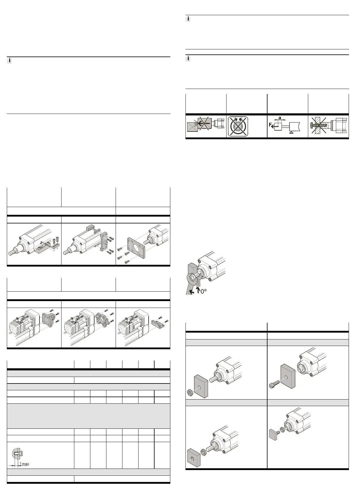
ESBF-... ESBF-...-F
Mounting via male thread Mounting via female thread
With nut With screw
– Guide unit EAGF
Instruction manual èwww.festo.com/sp.
With lock nut With lock nut
– Rod eye SGS, CRSGS
– Rod clevis SG, CRSG
– Coupling piece KSZ
– Selfaligning rod coupler FK; CRFK
Tab. 6 Overview of Attachment Component
 Loading...