Do you have a question about the Festo DGSL and is the answer not in the manual?
Key safety measures including environment, modifications, air supply, and repairs.
Specifies the product's authorized use for space-saving transport and slide operating mode.
Details improper operations such as missing cushioning or fixed stops and their consequences.
Outlines the necessary skills and experience for personnel operating the product.
Specifies minimum distances L1 and L2 from static and moving ferritic masses.
Guidance on positioning proximity switches within the provided slots.
Defines the minimum distance L for attaching cushioning components.
Details specific cushioning components and related torques for different DGSL variants.
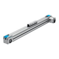
The Festo DGSL Mini Slide is a non-rotating single-piston drive with an integrated bearing guide, designed for space-saving transport of masses. Its primary function involves moving a slide back and forth through the alternate pressurization of its supply ports. The slide's movement is precisely controlled and brought to a halt at the end positions by shock absorbers. Depending on the specific variant, these cushioning components can be external elastic shock absorbers (for DGSL-...-E/-P/-P1), external hydraulic shock absorbers (for DGSL-...-Y3/-Y11), or no cushioning at all (for DGSL-...-N). The hydraulic shock absorbers also offer the capability to adjust the stroke, providing additional flexibility in application.
For optimal and safe operation, several usage features are critical. The product is intended for use in slide operating mode and must only be used in its original status without unauthorized modifications. Users must always observe the labeling on the product and take into consideration the ambient conditions at the location of use. Before any work is performed on the product, the compressed air supply must be switched off and locked to prevent accidental re-activation. It is crucial to use suitable cushioning components, as operating the product without them will result in damage and potential destruction of the slide if it moves without a fixed stop. The product should only be repaired by the Festo repair service. When tightening components, specified torques must be observed, with a general tolerance of ±20% unless otherwise specified.
Installation of the DGSL Mini Slide requires careful attention to detail. The product should be positioned to ensure that all operating elements, such as clamping components for shock absorbers, are easily accessible. It must be mounted without torsional stresses. If necessary, mounting components or accessories should be selected to prevent collisions by mounting them outside the positioning range. A suitable adapter plate must be chosen, and the slide moved to the retracted end position to access through-holes. Centring sleeves, which are included, must be used, and the product mounted according to the specific mounting type and stroke.
Attaching the yoke plate involves pushing a metal plate between the yoke plate and the housing as a counter holder, then pressing the centring pins into the yoke plate by hand. It is important not to hammer in the centring pins. When attaching the payload, it should be positioned on the yoke plate and then fastened with retaining screws.
For the installation of proximity switches, minimum distances (L1 and L2) between static and moving ferritic masses and the proximity switches must be observed to avoid faulty switching and external influences. The proximity switches are positioned in designated slots, with the lower slot used for DGSL-...-4 and DGSL-...-8 products. They are temporarily locked, and after a test run, mounted in the suitable position.
Rough setting of end positions involves manually positioning the slide at the desired end position, leaving it in the retracted end position during the setting procedure. The retaining screws of the fixed stop and the orifice are unscrewed. Some product variants allow for coarse adjustment of the front-end position, and a stroke reduction of up to two standard strokes is possible in combination with precision adjustment. The fixed stop is then replaced with the orifice, and the retaining screws are screwed in, observing the specified tightening torque. Precision adjustment of the end positions is then carried out on the cushioning components. Cushioning components for the DGSL-...-N product must be attached at both end positions.
Commissioning involves setting the speed of the slide using one-way flow control valves. L-shaped flow control valves on the front air port provide unhindered access for adjusting cushioning on smaller DGSL sizes. Transport covers on the supply ports must be removed, and tubing connected to the retract and advance supply ports. The connecting threads must be sealed, and alternative connections, if pre-assembled, must be sealed with blanking plugs.
Precision adjustment of the end positions requires checking the slide's correct positioning under compressed air and adjusting it as needed. This involves loosening clamping components, manually positioning the slide at the desired end position, and turning the cushioning component with a hex wrench until the end position is reached.
A test run is performed by positioning the payload on the slide, ensuring the center of gravity is as low as possible. One-way flow control valves are closed, then opened by one revolution. The drive is slowly pressurized with an on-off valve, causing the slide to move to an end position. A test run with a moveable mass is then started, taking into account the speed and acceleration of the moveable mass, the end position, the mass of the payload, and the position of the proximity switches. Changes should only be made when the slide is stationary. Finally, the one-way flow control valves are unscrewed until the required speed of the slide is reached. It is important to note that increased speed when approaching the end position can cause the slide to rebound.
Maintenance features are crucial for the longevity and reliability of the DGSL Mini Slide. Cushioning elements should be checked every 2 million cycles, and their cushioning length should be verified. If there are signs of wear, cushioning components must be replaced. They should also be replaced after a maximum of 5 million cycles.
For cleaning, the product should be wiped with a soft cloth, avoiding aggressive cleaning agents. For applications requiring reduced particle emission, abraded particles and soil should be removed from the product prior to initial commissioning and regularly during operation. Lubrication is also important, especially for longer lubrication intervals, at high temperatures, and with reduced particle emission. In these cases, a suitable lubricant should be used, such as Festo LUB-KC3, which can be applied by hand for even lubrication.
Troubleshooting information is provided to address common malfunctions. For instance, if the slide moves unevenly, the one-way flow control valves may be incorrectly set, or the tubing could be faulty. If the slide speed is too low, the air volume might be insufficient, or the flow control valve could be closed too much. If the slide stops in the end position without cushioning, the speed may be too high, or the cushioning could be too low. If the air cushion is not present, both supply ports might be pressurized simultaneously, or the exhaust could be blocked. If shock absorbers are faulty, they should be replaced. If the payload is too large, it should be reduced.
| Drive principle | Pneumatic |
|---|---|
| Mounting position | Any |
| Operating medium | Compressed air |
| Position sensing | Magnetic |
| Size | 8, 10, 12 |
| Switching current | 100 mA |
| Housing material | Anodised aluminium |
| Connection type | M8 connector or cable |
| Piston diameter | 8...25 mm |
| Operating pressure | 1.5...8 bar |
| Operating voltage | DC 10...30 V |