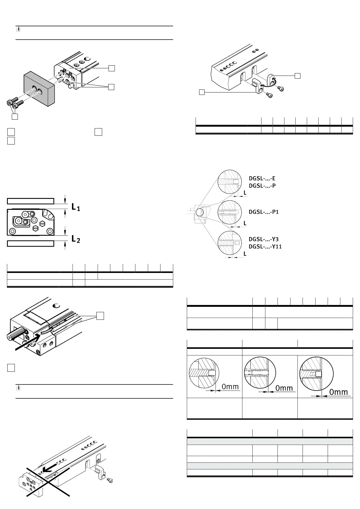
1. Push a metal plate [3] between the yoke plate [2] and the housing [1] as a
counter holder.
2. Press the centring pins [4] into the yoke plate [2] by hand.
Do not hammer in the centring pins.
7.3.2 Attaching the payload
Fig. 4: Attachment of the payload
Yoke plate
Centring pins
Retaining screws
1. Position the payload on the yoke plate [1] .
2.
Fasten the payload with the retaining screws [3].
8 Installation
8.1 Installation of proximity switches
To avoid faulty switching and external influences, observe the minimum distances
L
1
and L
2
between the static and moving ferritic masses and proximity switches.
Fig. 5:
Minimum distances
DGSL-... -4 -6 -8 -10 -12 -16 -20 -25
L
1
to ferric materials
[mm] 5 5 0
L
2
to ferritic materials
[mm] 15 0
Tab. 1:
Minimum distances
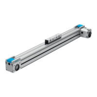
Fig. 6:
Position detection with proximity switch
Slots for proximity switches
1.
Position the proximity switches in the slots [1].
Use the lower slot for the DGSL-...-4 and DGSL-...-8 products.
2. Temporarily lock the proximity switch.
3.
After the test run, mount the proximity switch in the suitable position.
8.2 Rough setting of end positions
1.
Position the slide at the desired end position by hand. Leave the slide in the
retracted end position during the setting procedure.
2. Unscrew the retaining screws of the (fixed) stop
1 and the orifice 2.
– Certain product variants allow coarse adjustment of the front-end position
è
www.festo.com/catalogue.
–
A stroke reduction of max. 2 standard strokes is possible in combination
with the precision adjustment.
3. Replace the (fixed) stop 1 with the orifice 2.
4. Screw in the retaining screws. Observe the tightening torque.
DGSL-... -4 -6 -8 -10 -12 -16 -20 -25
Tightening torque [Nm] 0.76 1.3 1.3 2.9 2.9 6 9 9
5.
Carry out the precision adjustment of the end positions on the cushioning
components.
8.3
Installation of cushioning components
Cushioning components for the DGSL-…-N product must be attached at both end
positions.
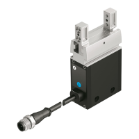
Fig. 7:
Minimum distance L of the cushioning components
DGSL-... -4 -6 -8 -10 -12 -16 -20 -25
Distance L with
DGSL-...-E/-P/-P1
[mm] 1 1.5
Distance L with
DGSL-...-Y3/-Y11
[mm] – – 1.5
Tab. 2:
Minimum distances
DGSL-...-E/-P DGSL-...-P1 DGSL-...-Y3/-Y11
no metallic stop metallic stop
The rubber buffer touches the
slide.
The stop sleeve touches the
slide against the force of the
cushioning.
The shock absorber housing/
reducing sleeve (with DGSL-...-
Y11) touches the slide against
the force of the shock absorber.
Tab. 3:
End position cushioning components
DGSL-... -4 -6 -8 -10
Only for DGSL-...-Y3
Max. torque, cushioning com-
ponent
[Nm] – – 0.5 0.8
Shock absorber DYSW-...-Y1F [Nm] – – 4 … 6 5 … 8
Only for DGSL-...-Y11
Max. torque reducing sleeve [Nm] – – – 0.8