6.
DGSL-... -4 -6 -8 -10
Max. torque cushioning com-
ponent
[Nm] – – – 0.5
Shock absorber DYSW-...-Y1F [Nm] – – – 4 … 6
Tab. 4: Tightening torque
DGSL-... -12 -16 -20 -25
Only for DGSL-...-Y3
Max. torque, cushioning com-
ponent
[Nm] 2.2 5 8 13
Shock absorber DYSW-...-Y1F [Nm] 7 … 10 8 … 14 10 … 17 12 … 20
Only for DGSL-...-Y11
Max. torque reducing sleeve [Nm] 2.2 5 8 13
Max. torque cushioning com-
ponent
[Nm] 0.8 2.2 5 8
Shock absorber DYSW-...-Y1F [Nm] 5 … 8 7 … 10 8 … 14 10 … 17
Tab. 5: Tightening torque
8.4
Installation
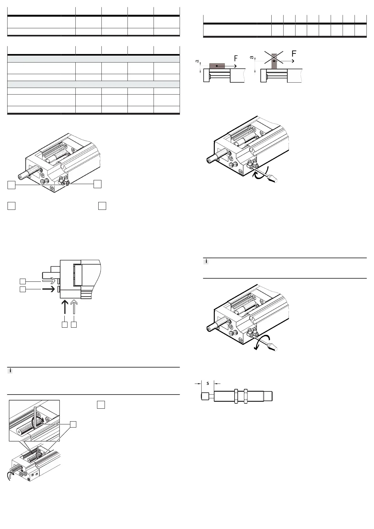
Fig. 8: Supply ports with one-way flow control valves
Supply port: retract
Supply port: advance
1.
Use one-way flow control valves to set the speed of the slide.
L-shaped flow control valves on the front air port permit unhindered access
for adjusting the cushioning with sizes DGSL-...-4 and DGSL-...-6.
2.
Remove the transport covers on the supply ports.
3.
Connect tubing to supply ports:
–
retract movement 1
–
advance movement 2
4.
The connecting threads must be sealed. The 3 and 4 alternative connec-
tions are pre-assembled on the DGSL. The alternative connections are sealed
with blanking plugs.
9 Commissioning
9.1 Precision adjustment of the end positions
Note
Check the correct positioning of the slide under compressed air. Correct the
positioning.
Fig. 9:
Position of the clamping
components
Clamping components
1. Loosen the clamping components [1].
2. Position the slide at the desired end position by hand.
3. Turn the cushioning component with a hex wrench until the end position is
reached.
4. Tighten the clamping component.
DGSL-... -4 -6 -8 -10 -12 -16 -20 -25
Tightening torque of
clamping component
[Nm] 0.15 0.2 0.3 0.8 1.2 2.5 2.5 3.5
9.2 Test run
Fig. 10: Positioning payload
1. Position the payload on the slide. Position the centre of gravity of the payload
as low as possible.
2. Close the one-way flow control valves.
3.
Open the one-way flow control valves by one revolution.
4.
Pressurise the drive. Slowly pressurise with an on-off valve.
Ä
The slide moves to an end position.
5.
Start a test run with a moveable mass.
Take the following into account in the test run:
– The speed and the acceleration of the moveable mass
– The end position
–
The mass of the payload
– The position of the proximity switches
7.
Only make changes when the slide is stationary.
8.
Unscrew the one-way flow control valves until the required speed of the slide
is reached.
An increased speed when approaching the end position can result in the slide
rebounding from the end position.
9.
Fix the proximity switches in the final positioning position.
10 Maintenance
10.1
Replacement of cushioning components
Fig. 11:
Cushioning distance s
1. Check the cushioning elements every 2 million cycles.
2.
Check the cushioning length s
è
12 Technical data
3. Replace the cushioning components if there are signs of wear.
4. Replace the cushioning components after max. 5 million cycles.
10.2 Cleaning
Clean the product with a soft cloth. Do not use aggressive cleaning agents.
For use with reduced particle emission:
– Remove abraded particles and soil from the product:
–
Prior to initial commissioning
– Regularly during operation