Do you have a question about the Festo FEC FC20 and is the answer not in the manual?
Consolidates safety instructions including caution and warning statements for operation.
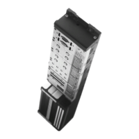
Briefly describes the compact controller's purpose in postprocessing digital data.
Details input terminals (0.0-0.7, 1.0-1.3), common potentials, RUN/STOP switch, and analog potentiometer.
Covers the Power LED and Status LED for Run/Stop/Error indication.
Details 24V/0V operating voltage terminals, relay outputs (0.0-0.7), and common connections.
Covers connection for extension (EXT) and serial port (COM).
Explains the COM port as an electrically isolated RS232 interface for programming with KSD2.
Describes the EXT port as a universal TTL connection, requiring an adapter for RS232 use.
Illustrates linking the IPC FEC FC20 directly to an external computer using the KSD2 cable.
Outlines requirements for 24V DC power supplies, isolation standards, and insulation resistance.
Details specifications for power relays, including mains voltage switching and insulation resistance.
Advises on separating signal input/output lines and avoiding bundled wires.
Emphasizes checking supply voltage, earth, and input/output connections before powering.
Stresses the importance of isolating supply voltages before changing cables or performing maintenance.
Recommends external and programmed interlocks for loads like motor contactors to prevent simultaneous activation.
Advises on using external switches for emergency stop functions to isolate on-load voltage.
Covers precautions for inductive loads and a warning about checking polarity before first use.
Covers following safety, wiring, and emergency stop instructions before initial setup.
Guides on connecting 24V DC operating voltage and at least one sensor to an input.
Details connecting actuators and switching on the 24V DC operating voltage, checking LEDs.
Explains connecting the KSD2 programming cable to the PC and FEC FC20 for programming.
Covers creating a new project, selecting the controller, and configuring I/O modules.
Details adding a program, compiling, and downloading the project to the controller.
Explains switching the controller to RUN mode and verifying input signals.
Provides physical dimensions, weight, operating/storage temperatures, and humidity.
Details operating voltage range, power consumption, cable length, and degree of protection.
Covers protection class, I/O connection type, wire cross-section, and tightening torque.
Specifies compliance standards for Electromagnetic Compatibility (EMC).
Details input number, configuration, voltage/current, signal logic, isolation, and cable length.
Covers output number, switchable voltages/currents, frequency, isolation, and current/loading.
Details the analog potentiometer range and specifications for Power LED and Status LED.
Specifies the number and software-dependent programmability of the RUN/STOP switch.
Details COM port connection, properties, and RS232/programming/universal interface settings.
Details EXT port connection, properties, and TTL/RS232 interface settings, including terminal assignments.
| Supply voltage | 24 V DC |
|---|---|
| Current consumption | 100 mA |
| Number of digital inputs | 8 |
| Number of digital outputs | 8 |
| Type of digital outputs | PNP |
| Output current | 0.5 A |
| Protection class | IP20 |
| Number of inputs | 8 |
| Number of outputs | 8 |
| Operating temperature | 0 °C to +55 °C |
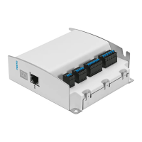
| Communication interface | Ethernet |
| Ambient temperature range | 0 °C to +55 °C |
| Weight | 0.5 kg |