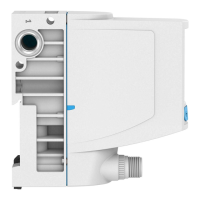
Fig. 4 Fitting, valve rear side
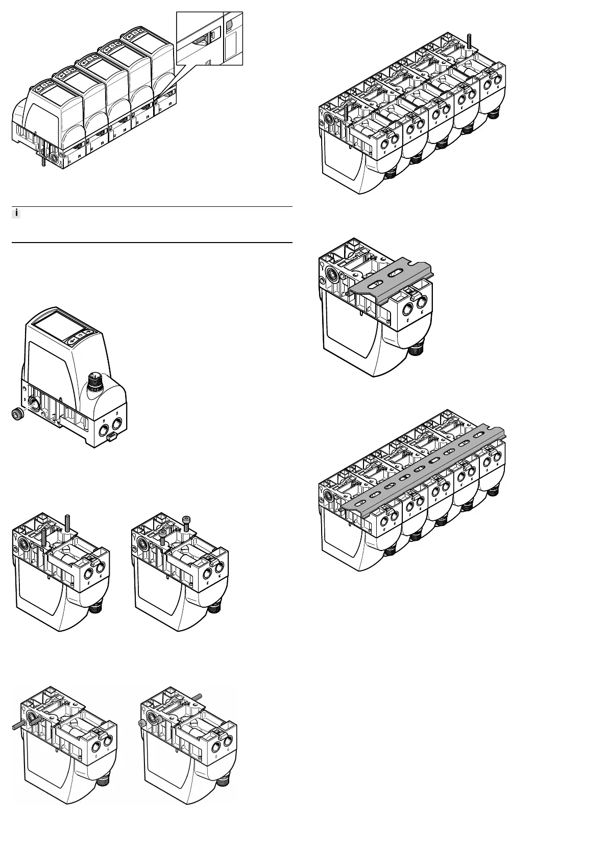
7.1.2 Creating Pressure Zones
In the case of pressure zone separation, connect the compressed air supply to
both ends of the valve manifold.
For pressure zone separation, the plug screw can be left in duct (1) of the valve.
Plug screws for duct (1) can also be ordered as accessories (VAME-P18-BP-
G18-P5) èwww.festo.com/catalogue.
1. Screw the plug screw into the duct (1) of the selected valve è Fig.5. Screw in
the plug screw until it is flush with the surrounding surface.
Fig. 5 Plug screw
2. Link valves.
7.2 Mounting
7.2.1 Mounting via Underside of Valve
Fig. 6 Mounting via underside of valve with M4 screws/M4 screws and square
nuts
7.2.2 Mounting via Side Surface
Fig. 7 Mounting via side surface with internal screws M4 / through screws M4
7.2.3 Mounting of Linked Valves
Fig. 8 Mounting of linked valves with lateral screws M4
7.2.4 Mounting on H-rail
Fig. 9 Individual valve
Fig. 10 Linked valves
7.3 Mechanical Installation
1. Make sure there is sufficient space for the connecting cable and tubing con-
nections.
Ä
This will prevent kinks from forming in the connecting cables and the
tubing.
2. Place the valve as close to the consumer as possible.
Ä
This leads to improved control precision and shorter response times.
8 Installation
8.1 Pneumatic Installation
Valves for Standard Operation (Overpressure)
1. Attach the tubing to the connections:
– Compressed air (1)
– Working air (2)
2. Fit a silencer at the exhaust air connection (3) or provide for ducted exhaust
air.
Valves for Vacuum Operation and Combined Vacuum / Overpressure Operation
(VPPI -...- 1V... H -...)
1. Attach the tubing to the connections:
– Vacuum (3)
– Working air (2)
2. Connect a compressed air supply to port (1) or mount a silencer to protect the
valve from coarse dirt particles.
 Loading...