6.2 Wall mounting (in-line valve)
VPPM-6L-... and VPPM-8L-...
• Fasten the VPPM-... [2] with 2 M4 screws. If necessary, use the bracket VAME-
P1-A [1].
– Tightening torque: 1.5 Nm
Only apply a static load to the VPPM-... when mounting the VPPM-... with the
assistance of the bracket.
VPPM-12L-...
•
Fasten the VPPM-… with 2 M5 screws.
– Tightening torque: 2.0 Nm
6.3 H.rail mounting (in-line valve)
VPPM-6L-... and VPPM-8L-...
1.
Attach the H-rail adapter VAME-P1-T [2] to the VPPM-... with 2 screws [1].
– Screws: M4 x 65 for VPPM-6L-..., M4 x 77 for VPPM-8L-...
–
Tightening torque: 1.5 Nm
2.
Attach the VPPM -... to the H-rail.
3. Fasten the VPPM-... with the retaining screw [2] of the H-rail adapter.
–
Tightening torque: 1.5 Nm
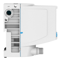
6.4 Manifold block assembly (sub base valve)
VPPM-6F-... and VPPM-8F-...
• Fasten the VPPM-... [2] to the manifold block [1] with 2 screws.
– Screws: M4 x 65 for VPPM-6F-..., M4 x 77 for VPPM-8F-...
– Tightening torque: 1.5 Nm
7
Installation
7.1
Pneumatic installation (in-line valve)
1. Remove the covers from the supply ports.
2. Connect the compressed air port (1) and the working air port (2) with tubing
è
Fig. 2.
3.
Fit a silencer at the exhaust air port (3) or install an exhaust air duct
è
Fig. 2.
Operating medium
NOTICE
Too much residual oil content in the compressed air will reduce the service life of
the valve.
• When using bio-oils (oils that are based on synthetic ester or native ester,
e.g. rapeseed oil methyl ester), the maximum residual oil content of 0.1 mg/m³
must not be exceeded (ISO 8573-1:2010 [–:–:2]).
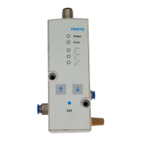
7.2 Electrical installation
WARNING
Risk of injury due to electric shock.
• For the electrical power supply, use only PELV circuits in accordance with IEC
60204-1/EN 60204-1 (Protective Extra-Low Voltage, PELV).
•
Observe the general requirements of IEC 60204-1/EN 60204-1 for PELV circuits.
• Only use voltage sources that ensure a reliable electric separation from the
mains network in accordance with IEC 60204-1/EN 60204-1.
NOTICE
Malfunction due to impaired immunity to interference
Long signal lines reduce the immunity to interference.
• Use the shortest possible signal lines.
NOTICE
•
The connector must not be twisted out of the intended position.
• The tightening torque of the M12 plug socket with cable must not exceed
0.5 Nm.
NOTICE
If the Y-connecting cable type NEBV-M12G8-KD-..-M12G5 is connected to CPX I/O
modules, galvanic isolation of the I/O modules will not be guaranteed.
1. Use the rating plate to check which valve variant is involved.
Valve variant VPPM-...-V1... VPPM-...-A4...
Voltage variant 0 … 10 V DC
Current variant 4 … 20 mA
2. Lay the electrical connection cable without crushing, kinking or stretching it.
3. If a shielded electrical connection cable is used, earth the shield at the end of
the cable remote from the valve.
4. Wire the VPPM-... according to the corresponding plug pattern.
VPPM-...-V1... VPPM-...-A4...