3.
1.
1.
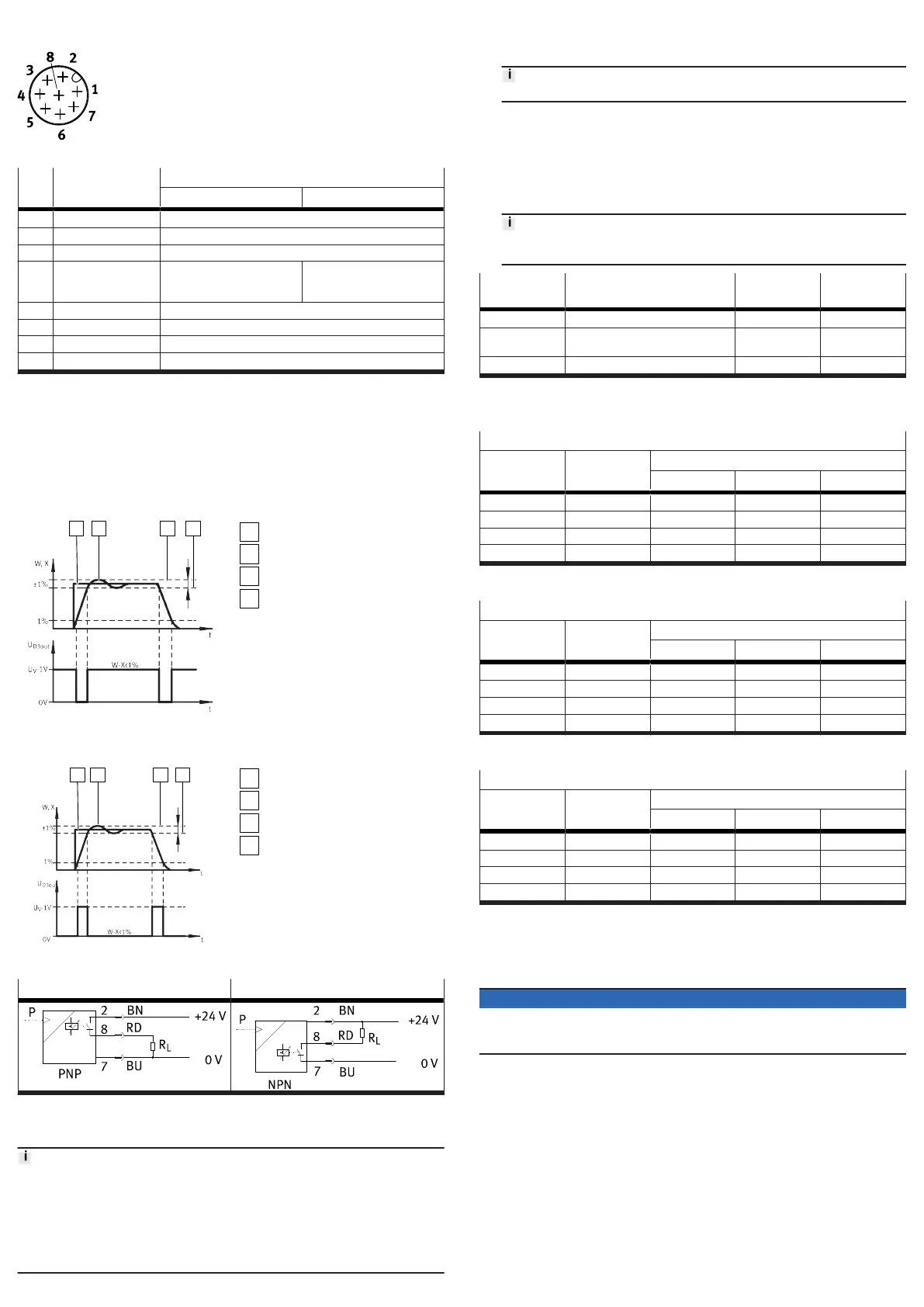
Pin allocation
The pins on the electrical connection are assigned as follows:
Fig. 5: Pin allocation
PIN Wire colour
1)
Port identifications
VPPM-...-V1... VPPM-...-A4...
1 white (WH) Digital input D1
2 brown (BN) +24 V DC supply voltage
3 green (GN) Analogue input W- (- setpoint value)
4 yellow (YE) Analogue input W+
(+ setpoint value)
0 … 10 V
Analogue input W+
(+ setpoint value)
4 … 20 mA
5 grey (GY) Digital input D2
6 pink (PK) Analogue output X (actual value)
7 blue (BU) GND supply earth
8 red (RD) Digital output D3
2)
1) With usage of the plug socket with cable as specified in accessories.
2) The hysteresis of the digital comparator output D3 is 0.5% FS.
Tab. 3: Pin allocation
Digital comparator output D3
The “Pressure reached” function permits monitoring of the pressure control func-
tion. The setpoint value is compared with the actual value.
The digital switching output D3 becomes active as soon as the divergence is
£ 0.5% FS and becomes inactive when the divergence > 1% FS is exceeded.
Graph for VPPM-...-...P switching variant
Fig. 6:
Switching variant VPPM-...-...P
Setpoint value
Actual value
Upper tolerance limit
Lower tolerance limit
Graph for VPPM-...-...N switching variant
Fig. 7:
Switching variant VPPM-...-...N
Setpoint value
Actual value
Upper tolerance limit
Lower tolerance limit
Circuit diagram VPPM-...-...P Circuit diagram VPPM-...-...N
Tab. 4:
VPPM-... circuit diagrams Switching output
8
Commissioning
•
Keep high-frequency radiation away from the VPPM-... in order to avoid
increased tolerances of the outlet pressure.
• The VPPM-... interprets setpoint signals that are less than 1% Full Scale (FS) as
0 V or 4 mA. In this case the working pressure is set to ambient pressure.
• At typical input values below 3.6 mA , the valve detects a cable break and the
last pressure set remains unregulated. Leakage results in a change of pressure
over the long term.
1. Connect the VPPM-... with a setpoint value signal. The VPPM-... has a differen-
tial input. Apply the setpoint signal 0 … 10 V or 4 … 20 mA to contacts 3 and 4.
Apply the lower potential to contact 3 and the higher potential to contact 4.
Contact 3 (– setpoint value) can be connected to contact 7 (GND).
2. Power the VPPM-... with direct current.
– Supply voltage UV = 24 V DC ±10%
Select a parameter set for the regulator.
– Press and hold the [Edit] key for 3 seconds.
–
Select a parameter set with the [UP] and [DOWN] keys. The LED of the
selected parameter set lights up.
– Press the [Edit] key to confirm the selection.
The control response of the VPPM-... can also be set by remote control via
digital inputs D1 and D2.
Parameter set Control response Input D1 (PIN
1)
Input D2 (PIN
5)
1 Fast control response 1 (24 V DC) 0 (0 V DC)
2 Factory setting: universal control
response
0 1
3 Precise control response 1 1
Tab. 5: Parameter sets
The following 3 tables show the recommended parameter sets for the different
pneumatic ports:
Parameter sets recommended for VPPM-6...
Tube length
1)
Open system Output volume in ml
0 … 100 100 … 1000 >1000
0 m 3 3 2 1
1 m 3 3 2 2
3 m 3 3 3 2
³ 5 m 3 3 3 2
1)
with inner tubing diameter 6 mm or 8 mm
Tab. 6: Parameter sets recommended for VPPM-6...
Parameter sets recommended for VPPM-8...
Tube length
1)
Open system Output volume in ml
0 … 500 500 … 2000 >2000
0 m 3 1 2 3
1 m 3 1 2 3
3 m 3 2 3 3
³ 5 m 3 3 3 3
1)
with tubing diameter 8 mm or 10 mm
Tab. 7: Parameter sets recommended for VPPM-8...
Parameter sets recommended for VPPM-12L-...
Tube length
1)
Open system Output volume in ml
0 … 2000 2000 … 10000 >10000
0 m 3 1 2 3
1 m 3 1 2 3
3 m 3 2 3 3
³ 5 m 3 3 3 3
1)
with tubing diameter 12 mm or 16 mm
Tab. 8: Parameter sets recommended for VPPM-12L-...
9 Maintenance
9.1 Disassembly
NOTICE
•
When switching off the VPPM.-..., first make sure that the setpoint value is set
to 0, then that the supply pressure and finally the supply voltage are switched
off.
Switch off the following energy sources:
– Operating voltage
–
Compressed air
2. Disconnect the connections from the device.
3.
Remove the device from the mounting surface or H-rail.
9.2
Cleaning
Switch off the following energy sources to clean the outside:
– Operating voltage
–
Compressed air
2. Clean the device on the outside with a soft cloth as required.
 Loading...