10 Malfunctions
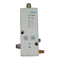
Status of the LED displays
Cause Green LED [power] Red LED [error]
– Undervoltage or overvoltage
of the setpoint value
on on
– Hardware error
– Overvoltage (> 30 V)
– Internal temperature too
high
on flashes
– Undervoltage (< 18 V) off off
Tab. 9: Status of the LED displays
Fault clearance
Malfunction Possible cause Remedy
Device does not respond No supply voltage, LED [power]
off.
Check the connection of the
supply voltage 24 V DC.
No data communication.
–
Check control unit.
– Check connection.
Flow rate too low Restriction of the flow cross
section by connection tech-
nology.
Use alternative connections.
Pressure rise too slow Large cylinder volume and long
tube length.
Select another parameter set.
Pressure constant despite
modified setpoint specification
Break in the electrical con-
necting cable.
Replace supply cable.
Supply pressure P1 too low. Increase supply pressure.
Manual selection of parameter
sets with the [UP] and [DOWN]
keys on the device is not pos-
sible
Voltage is applied at digital
inputs D1 and D2.
Apply 0 V DC at digital inputs
D1 and D2.
Tab. 10: Fault clearance
11
Technical data
General technical data
Design Proportional-pressure regulator
Mounting position As desired, preferably horizontal (display elements
facing upwards)
Materials
Housing Wrought aluminium alloy
Cover PAXMD6 GF50/gr-P
Seals Nitrile rubber
Lubrication silicone-free
Weight
VPPM-6... [g] 400
VPPM-8... [g] 560
VPPM-12... [g] 2050
Tab. 11:
General technical data
Operating and environmental conditions
Medium Compressed air in accordance with ISO 8573-1:2010
[7:4:4] inert gases
Information on operating
medium
Lubricated operation not possible
Degree of protection IP 65 when mounted, with tightened mounting screws,
in combination with plug socket according to accesso-
ries.
Ambient temperature [°C] 0 … 60
Temperature of medium [°C] 10 … 50
Storage temperature [°C] –10 … +70
Vibration and shock
Vibration Tested in accordance with DIN/IEC
68/EN 60068 Part 2-6; wall mounting: 0.35 mm path
at 10 … 60 Hz, 5 g acceleration at 60 … 150 Hz
1)
Shock Tested in accordance with DIN/IEC
68/EN 60068 Part 2-27; wall mounting: ±30 g at 11 ms
duration; 5 shocks per direction
1)
1)
Information does not apply when mounting the VPPM-.../VPPX-... on bracket VAME-P1-A/-T.
Tab. 12: Operating and environmental conditions
VPPM-... 0L2H 0L6H 0L10H
Pressure ranges
Permissible input pressure P1 [MPa] 0 … 0.4 0 … 0.8 0 … 1.1
[bar] 0 … 4 0 … 8 0 … 11
[psi] 0 … 58 0 … 116 0 … 159.5
Control range (output pressure
P2)
1)
[MPa] 0.002 … 0.2 0.006 … 0.6 0.01 … 1
[bar] 0.02 … 2 0.06 … 6 0.1 … 10
[psi] 2.9 … 29 8.7 … 87 1.45 … 145
Total leakage when new [l/h] < 5
Connection G 1/8, 1/8 NPT, G 1/4, 1/4 NPT, G 1/2, 1/2 NPT
VPPM-... 0L2H 0L6H 0L10H
Nominal width
Pressurisation [mm] 6 for VPPM-6...
8 for VPPM-8...
12 for VPPM-12...
Exhaust port [mm] 4.5 for VPPM-6...
6 for VPPM-8...
12 for VPPM-12...
1)
Input pressure P1 at least 0.1 MPa (1 bar, 14.5 psi) above output pressure P2.
Tab. 13: Characteristic pneumatic values
Characteristic electrical values
Electrical connection Pin contact M12x1, 8-pin
Permissible operating voltage [V DC] 21.6 … 26.4
Permissible residual ripple max. 10%
Power rating of digital switching
output D3 (PIN 8 in el. connection)
[mA] max. 60
Max. permissible supply line
length and signal line length
[m] 10
Max. electrical power consumption
VPPM-6... and VPPM-8... [W] 7
VPPM-12L-... [W] 12
Voltage type VPPM-...-V1...
Setpoint variable [V DC] 0 … 10
Input resistance (setpoint value) [kΩ] 10
Output actual value load [kΩ] min. 2
Current type VPPM-...-A4...
Setpoint variable [mA] 4 … 20
Input resistance (setpoint value) [Ω] 250
Output actual value load [Ω] max. 500
Tab. 14:
Characteristic electrical values
Control characteristics
1)
Linearity 1% Full Scale (FS)/2% Full Scale (FS)
Hysteresis 0.5% Full Scale (FS)
Reproducibility 0.5% Full Scale (FS)
Total accuracy 1.25% (S1)/2.25 (2%)
Temperature coefficient 0.04/K
1)
Maximum deviation, characteristic values determined at room temperature in accordance with ISO 10094.
Linearity refers to the ideal characteristic curve.
Tab. 15: Control characteristics
 Loading...