10
AP-KA 65
GB
Original operating manual
1Technical data
*
Depending on material
2Symbols
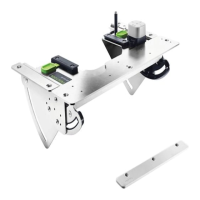
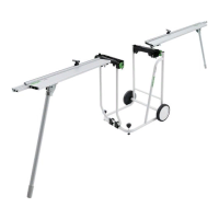
3 Machine features
The specified illustrations appear at the beginning
of the Operating Instructions.
4 Intended use
The adapter plate AP-KA 65 is designed for station-
ary use of the edge bander KA 65 as well as attach-
ing edge bands made from wood, materials with
similar properties to wood and plastic.
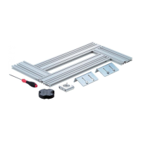
Adapter plate installation options:
– in perforated board LP-KA 65 MFT/3 in conjunc-
tion with multifunction table MFT/3,
– in cut-out in a separate work plate and a suitable
bench according to Festool installation instruc-
tions.
The user is liable for improper or non-in-
tended use.
5 Safety instructions
Warning! Read and observe all information
and safety instructions.
Ignoring warning notes
and instructions may lead to electric shocks, fires
and/or cause serious injury.
Keep all safety information and other instructions
in a safe place for future reference.
5.1 Machine-related safety instructions
– Observe the operating instructions for the edge
bander KA 65 and multifunction table MFT/3 to
avoid dangers and accidents.
– Make sure that all rotary knobs
[1-7]
are tight-
ened before starting work.
6Setup
Observe the operating instructions for the
multifunction table MFT/3.
Ensure that the floor around the machine is
level, in good condition and free of loose ob-
jects (e.g. chips and offcuts).
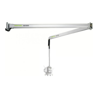
7 Installation in perforated board
LP-KA 65 MFT/3
7.1 Fitting the adapter plate [2]
Install the components as follows:
Screw the stationary fixture
[1-3]
to the angle
adapters
[1-5]
.
Screw the metal bridge
[1-2]
over the stationary
fixture
[1-3]
.
Screw the guide pin
[1-9]
and the guide rail
adapter
[1-11]
onto the stationary fixture
[1-3]
.
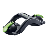
7.2 Installing the edge bander
The edge bander can now be secured in the adapter
plate:
Release the rotary angle adjustment knobs
[1-
7]
by turning anticlockwise
[3]
.
Adjust the angle scale
[1-10]
to 45°
[3]
.
Tighten the rotary angle adjustment knobs
[1-7]
by turning clockwise
[3]
.
Slide the edge bander to the right and left in the
guides
[1-8]
[4]
.
Secure the edge bander using the sealing slides
[1-6]
[5]
.
Release the rotary angle adjustment knobs
[1-
7]
by turning anticlockwise
[6]
.
Adjust the angle scale
[1-10]
to 0°
[6]
.
Tighten the rotary angle adjustment knobs
[1-7]
by turning clockwise
[6]
.
Adapter plate AP-KA 65
Infinitely adjustable angle 0° - 45°
Edge height 18 - 65 mm
*
Edge thickness 0,5 - 3,0 mm
*
Warning of general danger
Manual, read the instructions
Do not throw in the household waste.
Tip or advice
[1-1]
Guide plates (15 x)
[1-2]
Metal bridge
[1-3]
Stationary fixture
[1-4]
Additional roller
[1-5]
Angle adapters
[1-6]
Sealing slide
[1-7]
Rotary knobs for angle adjustment
[1-8]
Guides
[1-9]
Guide pin
[1-10]
Angle scale
[1-11]
Guide rail adapter
 Loading...