AP-KA 65
11
GB
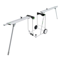
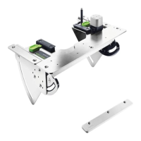
7.3 Fitting the guide plates [7]
The guide plates
[1-1]
are mounted on the perfo-
rated board according to the size and shape of the
workpiece to ensure safe guidance of the work-
piece and prevent it from tipping.
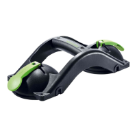
7.4 Fitting the additional roller [7 A]
The additional roller
[1-4]
can be fitted to help
guide the machine more accurately along long
workpieces.
Turn clockwise to mount securely in position.
Unscrew anticlockwise to remove.
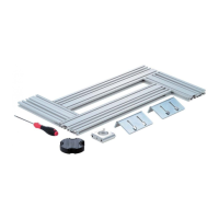
8 Installing in a separate work plate
The Festool installation instructions contain:
– Dimensions of the cut-out for the adapter plate
– Dimensions of the hole pattern for positioning
the guide plates
After preparing the separate work plate, you
can continue fitting the other elements as de-
scribed in
chapter
7
.
9 Settings
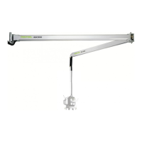
9.1 Adjusting the guide rail adapter [8]
The guide rail adapter
[1-11]
can be adjusted to
match the thickness of the edge band. The distance
between the workpiece and the adhesive roll can be
adjusted depending on the setting selected.
Lift the guide rail adapter
[1-11]
.
Change the setting to adjust the guide rail
adapter
[1-11]
to the thickness of the edge.
Lower the guide rail adapter
[1-11]
and engage
in position.
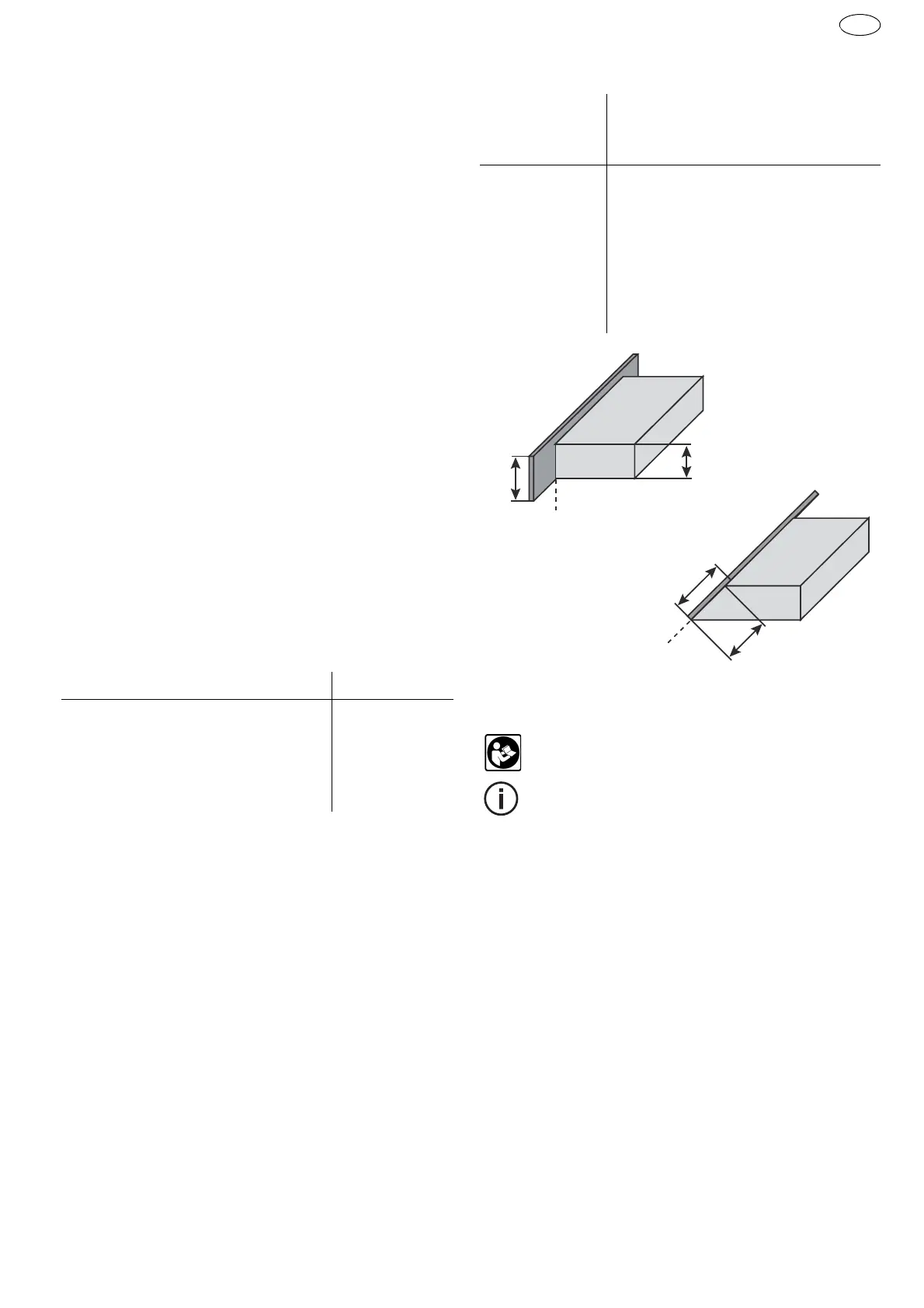
9.2 Adjusting the angle scale [1-10]
The angle scale
[1-10]
can be used to adapt the an-
gle of the stationary fixture to the sloping surface of
the workpiece.
Release the rotary angle adjustment knobs
[1-
7]
by turning anticlockwise
[3]
.
Set the angle.
Tighten the rotary angle adjustment knobs
[1-7]
by turning clockwise
[3]
.
Overview of required edge band width in relation
to the workpiece height and angle setting
9.3 Edge bander settings
Observe the operating instructions for the
edge bander KA 65.
The edge bander
cannot be moved to purg-
ing position
in the stationary fixture! In order
to carry out purging, the edge bander must
be removed from the stationary fixture.
10 Working with the machine
10.1 Attaching the edge band
Guide the edge band behind the guide pin
[1-9]
on the edging infeed to prevent the edge band
from slipping at the preset angle during the glu-
ing process
[9]
.
Press the start button on the edge bander once
to start feeding in the edging
[9]
.
Position the workpiece on the guide rail adapter
[1-11]
[10]
.
Press the start button on the edge bander again
and wait until adhesive visibly appears on the
edge band
[10]
.
Push the workpiece from right to left past the
edge bander while applying pressure on the
contact roller
[11]
.
Thickness of the edge band in mm Setting
0.5 - 0.8 0.5
0.8 - 1.3 1
1.3- 2.3 2
2.3- 3.0 3
Workpiece
height (h1) in
mm
Minimum height of the edge band
(h2) in mm for angle setting
0° 22.5° 45°
18
22 24 31
22
26 29 37
25
29 32 41
28
32 35 46
38
42 46 60
45°
 Loading...