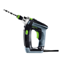
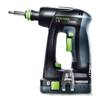
5 Parts of the machine
[1-1]
Torque thumbwheel
[1-2]
Bit store
[1-3]
LED light
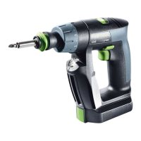
[1-4]
Gear switch
[1-5]
Drilling symbol
[1-6]
Screwdriving symbol
[1-7]
Screwdriving/drilling selector switch
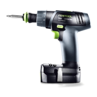
[1-8]
Rotational direction switch
[1-9]
On/off switch
[1-10]
Belt clip
[1-11]
Buttons for releasing the battery pack
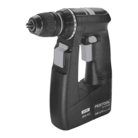
[1-12]
Insulated gripping surfaces (grey
shaded area)
[1-13]
Capacity indicator
Accessories shown or described are not always
included in the scope of delivery.
The specified illustrations appear at the begin
ning of the Operating Instructions.
6 Operation
6.1 Belt clip
The belt clip allows a shot-term securing of the
device in the work clothes. Insert the belt clip
on the designated side, right or left, and fix it
with the screw
[1a].
6.2 Switching on/off [1-9]
Press = ON, release = OFF
The speed can be infinitely adjusted,
relative to the pressure applied to the
on/off switch.
The LED light [1-3] lights up when the on/off
switch [1-9] is pressed.
7 Battery pack
► Inserting the battery pack [2a]
► Removing the battery pack[2b]
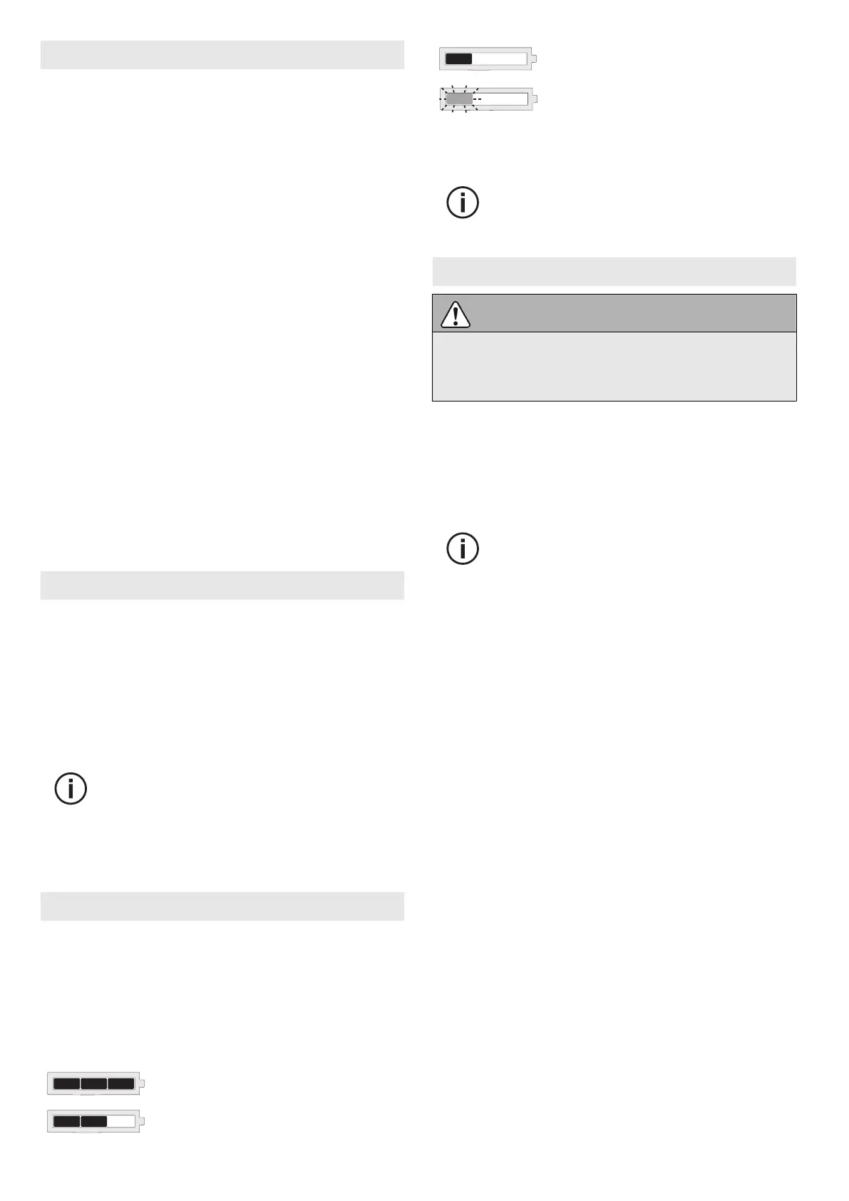
7.1 Capacity indicator
The capacity display indicates the charge of the
battery pack for approx. 2 seconds after the
button
is pressed:
70–100%
40–70%
15–40%
< 15%
*
*
Recommendation: Charge the battery pack
before any further use.
Further information about the battery
pack and charger can be found in the
corresponding operating manual.
8 Settings
CAUTION
Risk of injury
► Only adjust the settings when the power
tool is switched off.
8.1 Changing direction of rotation [1-8]
• Switch to the left = clockwise rotation
• Switch to the right = counterclockwise rota
tion
8.2 Changing gear [1-4]
Only actuate the gear switch with the
tool switched off. Otherwise there is a
risk of damaging the gear unit.
• Gear switch forwards (digit 1 visible) =
1st gear
• Gear switch to rear (digit 2 visible) =
2nd gear
8.3 Fastening
Adjust the switch so that its marking [1-7]
faces the screw symbol [1-6].
Adjust the torque accordingly at the torque
wheel
[1-1].
Position 1 = low torque
Position 25 = high torque
An acoustic signal sounds when the preset tor
que is reached and the machine then switches
off. You must release and press the ON/OFF
switch [1-9] again to start the machine.
8.4 Drilling
Adjust the switch [1-7] so that its marking
faces the drilling symbol [1-5]. Maximum tor
que is set in this position.
English
14
 Loading...