Page 5
The FDL242 contains software that processes the output of the detector and generates a Fire and Fault status. This status is transmitted to the
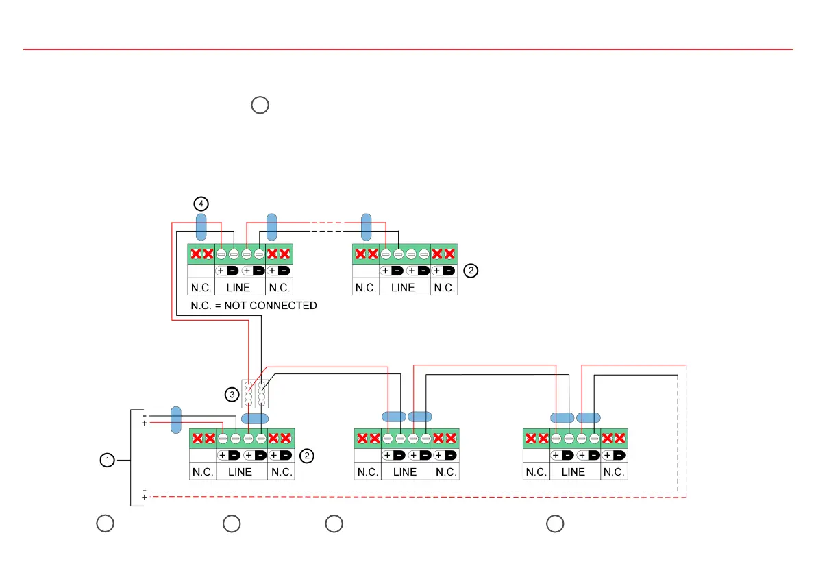
Siemens Fire Control Panel (FCP) over FDnet/C-NET which also powers the FDL242. To wire a detector to a FCP, use the following wiring
diagram. NOTICE: Install one cable ferrite 4 on each cable entry to the detector.
3. Wiring Information
Use of Unshielded Cables
The connection is established from base to base using twisted or non-twisted wire pairs.
Control Panel
1
Detector
2
Auxiliary Terminals DBZ1190-xx
3
Cable Ferrite
4