Some applications require an attic floor installation of the
horizontal unit. In this case the unit should be set in a full size
secondary drain pan on top of a vibration absorbing mesh.
The secondary drain pan prevents possible condensate
overflow or water leakage damage to the ceiling. The
secondary drain pan is usually placed on a plywood base
isolated from the ceiling joists by additional layers of vibration
absorbing mesh. In both cases, a 3/4” drain connected to this
secondary pan should be run to an eave at a location that will
be noticeable. If the unit is located in a crawl space, the
bottom of the unit must be at least 4” above grade to prevent
flooding of the electrical parts due to heavy rains.
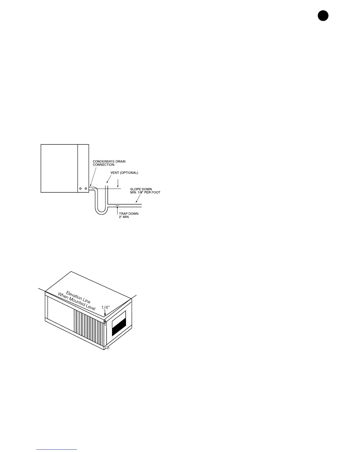
CONDENSATE DRAIN:
A drain line must be connected to the heat pump and pitched
away from the unit a minimum of 1/8” per foot to allow the
condensate to flow away from the unit.
This connection must be in conformance with local plumbing
codes. A trap must be installed in the condensate line to
insure free condensate flow. (Heat Pumps are not internally
trapped). A vertical air vent is sometimes required to avoid air
pockets. (See Figure #3). The length of the trap depends on
the amount of positive or negative pressure on the drain pan.
A second trap must not be included.
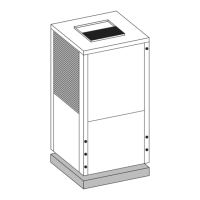
The horizontal unit should be pitched approximately 1/4”
towards the drain in both directions, to facilitate condensate
removal. (See Figure #4)
DUCT SYSTEM:
All EV models are provided with a return air duct flange and a
supply air outlet collar to facilitate duct connections. Refer to
the individual data specification sheet for physical dimensions
of the collar and flange.
A flexible connector is recommended for supply and return air
connections on metal duct systems. All metal ducting should
be insulated with a minimum of one inch duct insulation to
avoid heat loss or gain and prevent condensate forming during
the cooling operation. Application of the unit to uninsulated
duct work is not recommended as the unit’s performance will
be adversely affected. Do not connect discharge ducts directly
to the blower outlet. The factory provided air filter must be
removed when using a filter back return air grill.The factory
filter should be left in place on a free return system.
If the unit will be installed in a new installation with new duct
work, the installation should be designed using current
ASHRAE procedures for duct sizing. If the unit will be
connected to an existing duct system, a check should be
made to assure that the duct system has the capacity to
handle the air required for the unit application. If the duct
system is too small, larger duct work must be installed. Be
certain to check for existing leaks and repair.
The duct system and all diffusers should be sized to handle
the designed air flow quietly. To maximize sound attenuation
of the unit blower, the supply and return air plenums should
be insulated. There should be no direct straight air path thru
the return air grille into the heat pump. The return air inlet to
the heat pump must have at least one 90 degree turn away
from the space return air grille. If air noise or excessive air flow
are a problem, the blower speed can be changed to a lower
speed to reduce air flow.
ELECTRICAL:
All field wiring must comply with local and national fire, safety
and electrical codes. Power to the unit must be within the
operating voltage range indicated on the unit’s nameplate. On
three phase units, phases must be balanced within 2%.
Properly sized fuses or HACR circuit breakers must be
installed for branch circuit protection. See equipment rating
plate for maximum size. The unit is supplied with an opening
for attaching conduit. Be certain to connect the ground lead to
the ground lug in the control box. Connect the power leads as
indicated on the unit wiring diagram.
NOTE: Units supplied with internal electric heat require two
(2) separate power supplies. One for the unit compressor
circuit and one for the electric heater elements which also
powers the unit blower motor and control circuit.
Refer to the ELECTRIC HEATER PACKAGE OPTION section
on page 6 and figure #8. for wiring instructions, minimum
circuit ampacities and maximum fuse/breaker sizing.
THERMOSTAT CONNECTIONS:
Thermostat wiring is connected to the 7-position low voltage
terminal block located in the upper portion of the electrical
box. The thermostat connections and their functions are as
follows:
C Transformer 24 VAC Common
O Reversing Valve (energized in cooling)
Y Compressor contactor
R Transformer 24 VAC Hot
W2 Auxiliary Electric Heat (2
nd
stage heat) runs in
conjunction with the compressor
G Fan
E Emergency heat
3
EV SERIES
(Figure #3)
(Figure #4)