Do you have a question about the FIAM. eTensil and is the answer not in the manual?
Indicates product must be disposed of separately according to WEEE Directive.
Operator must refer to manual when this danger symbol appears.
Requires reading the instruction manual before using the product.
Screwdriver conforms to IEC 61340-5-1 Standard for EPA areas.
Indicates product conforms to applicable EU Directives.
Ensures a clean, well-lit, and safe work environment, keeping children away.
Covers proper plug use, avoiding contact with earthed surfaces, and cord care.
Emphasizes attention, safety equipment, avoiding accidental activation, and proper clothing.
Guidelines on not forcing the tool, proper switch use, and unplugging for adjustments.
Includes advice on qualified repair, spare parts, and clamping for high torques.
Instructions for connecting the tool power cable and supply unit cable.
Warnings about connecting with the unit switched off and using earthed mains supply.
Explanation of LED status for left/right rotation and how to change direction.
Details on adjusting torque by varying clutch spring compression using the adjuster key.
Warning to keep the adjustment slot closed during use to prevent injury or damage.
Configuration parameters accessed by holding the reverse button for over 4 seconds.
Table detailing functions based on lever presses (e.g., Lever start, Push-to-start).
Instructions for holding the tool firmly and clamping it to a reaction arm for torques > 4Nm.
Warning against clamping the tool at incorrect points to avoid damage and ensure operation.
Details the color and function of each LED (e.g., clutch triggered, tool speed, status).
Instructions on using the button to switch between high (H) and low (L) tool speeds.
Description of signals available on the DB15 connector for the TPU-2 model.
Information on tool inspection after 1 million cycles and how to reset the signal.
Rules for correct system operation, including minimum pause between tightening cycles.
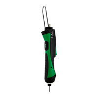
| Brand | FIAM. |
|---|---|
| Model | eTensil |
| Category | Power Screwdriver |
| Language | English |