INSTRUCTIONS FOR
USING THE REMOVABLE
BALL HEAD TOW BAR
37) 38) 39) 40) 41) 42)
Before setting off, check the correct
locking of the removable ball head tow
bar, as follows:
❒ The green mark of the flywheel must
coincide with the green mark on the
tow bar.
❒ The flywheel is in the stop position on
the tow bar (without slot).
❒ Locked lock and key removed. The
flywheel cannot be removed.
❒ Ball head bar firmly secured to the
housing pipe. Check by shaking
with a hand.
The fitting procedure must be repeated
if any of the 4 checked requirements
is not met.
If even only one of the requirements is
not met the tow hook must not be
used, as in this case there is risk of
accidents. Contact the joint
manufacturer.
The ball head tow bar can be fitted and
removed manually, without needing
any tool.
Never use working tools or means, as
the mechanism could be damaged.
Never unlock in the case of trailer
attached to the vehicle or fitted rack.
When driving without trailer or rack the
ball head tow bar must be removed
and the closing plug must always
be inserted in the housing pipe. This
applies particularly if the visibility of the
number plate characters or of the
lighting system is reduced.
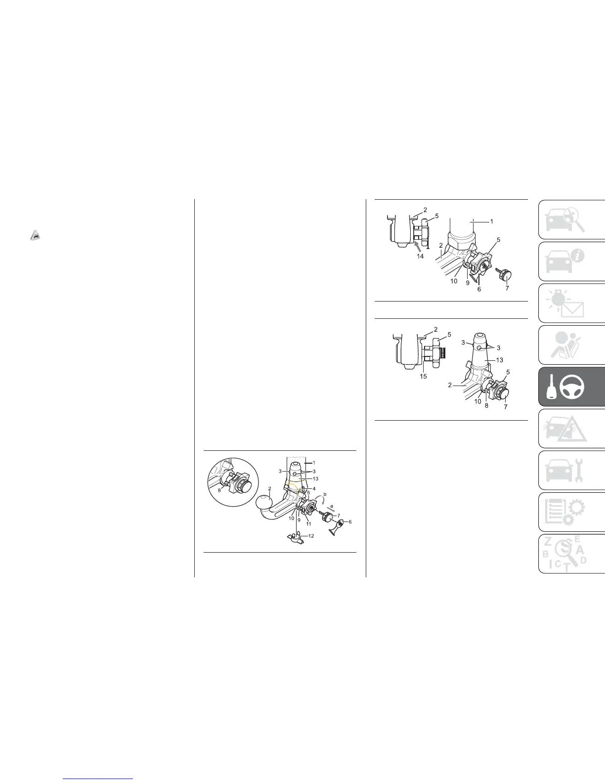
Removable ball head
tow bar fig. 176 - fig. 177 - fig. 178
1. Housing pipe - 2. Ball head tow bar
- 3. Locking balls - 4. Release lever -
5. Flywheel - 6. Cap - 7. Key - 8. Red
mark (flywheel) - 9. Green mark
(flywheel) - 10. Green mark (tow bar) -
11. Symbol (control release) - 12.
Closing plug - 13. Coupling pin - 14.
No slot between 2 and 5 - 15. Slot
of approx. 5 mm
.
.
176
F1A0380
177 - Locked position, driving
F1A0381
178 - Released position, removed
F1A0382
195