Fiber Options Inc., 80 Orville Drive, Bohemia, NY 11716-2533
Phone: 516-567-8320 or 1-800-342-3748; Fax: 1-877-FiberFax (1-877-342-3732 toll free) or 516-567-8322
Internet: www.fiberoptions.com Email: info@fiberoptions.com Rev 031401
S711F2F Fiber Optic Data Transmission Link
For Casi Rusco Access Control Systems
n S711F2F system can consist of (a) one transmitter and one
receiver operating over one fiber or (b) two transceivers operating
over two fibers. The relay contacts are rated for 150 V, 0.5 A, 10 W
max. The units require no setup adjustments.
Data Connections: The data connector is a removable screw
terminal connector attached at the rear of the housing. Pin numbering
is in descending order from 8 at the top to 1 at the bottom. Remove
the connector from the unit and attach the data connections according
to Table 1.
Fiber Connections: Each unit has one optical connector at the rear
end of the housing. Connect the fiber to these connectors.
Power Connections: The power connector is a removable screw
terminal connector attached at the rear of the housing. Pin numbering
is identified on the housing. Refer to Table 2 or to the labeling on the
housing for pin connection polarities and voltages.
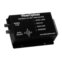
LED Indicators: Each unit is equipped with a set of diagnostic LEDs
that provide extensive information about performance and activity on
the link. Refer to Table 3 for a key to the LED functions.
. . . light years ahead
AD01-002/