Do you have a question about the Fiber Options S711D and is the answer not in the manual?
Overview of S711D/S7711D series, fiber types, and system configurations.
Illustrates data flow and fiber connections for the universal data transmission system.
Advice on mounting, environment, and screw types for modules.
Guides for installing standalone modules and rack cards in enclosures/cages.
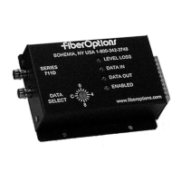
Identifies connectors, switches, and LEDs on rackmount cards and standalone modules.
Explains rotary switch settings for data format selection.
Provides physical dimensions for 2-fiber and single-fiber standalone modules.
Pinout tables for RS232, TTL, and RS422 connections on rack cards.
Pinout tables for RS485, Manchester/Biphase, and test mode connections on rack cards.
Pinout tables for RS232, TTL, and RS422 connections on standalone modules.
Pinout tables for RS485, Manchester/Biphase, and test mode connections on standalone modules.
Specific installation steps and cautions for card cages and standalone enclosures.
How to select data formats and utilize the system's data translation features.
Configuration of the alarm jumper and guidelines for connecting data and fiber optic cables.
How to connect power to standalone modules and rack systems.
Overview of operation, basic maintenance, and technical support contact.
Detailed notes on RS485 wiring, biasing, tri-state conditions, and termination.
Steps and expected behavior for verifying system operation using test mode.
How the system manages RS485 bus contention and failure states.
Explains the function and meaning of LEVEL/LOSS, DATA IN, DATA OUT, and ENABLED LEDs.
Table summarizing various data signal conversions between protocols.
Table summarizing LED names, colors, and their operational indications.
Description of the S711F2F system for access control, its capabilities and ratings.
Details on connecting data, power, and fiber for the S711F2F using screw terminals.
Refers to Table 3 for a key to the LED functions for the S711F2F.
Pinout details for the data connector on the S711F2F unit.
Pinout details for the power connector on the S711F2F unit.
Explains the meaning of each LED indicator for the S711F2F.
| Brand | Fiber Options |
|---|---|
| Model | S711D |
| Category | Microphone system |
| Language | English |