nc = no connection
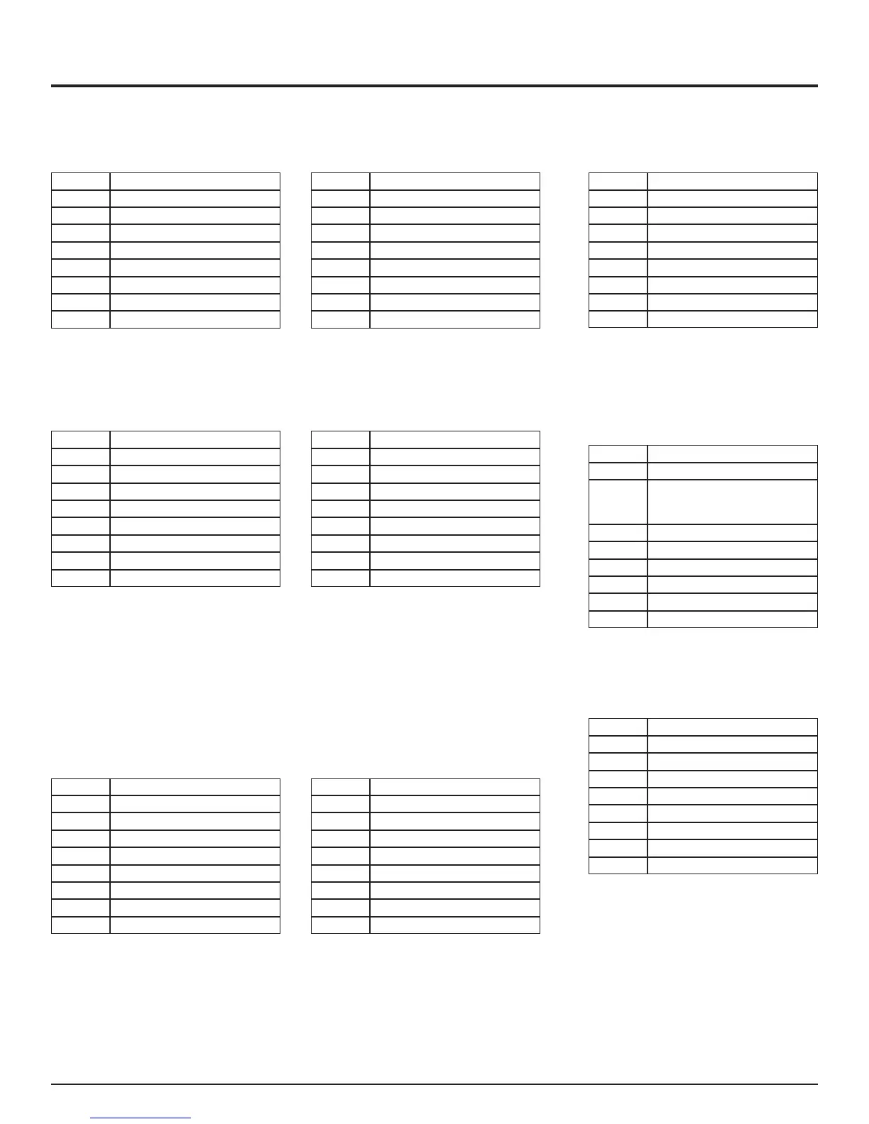
8-PIN DATA CONNECTION TABLES - RACK-MOUNT CARDS - S711D S7711D
Pin No.
Function
8 Ground
7 nc
6 nc
5 RS232 IN
4 nc
3 nc
2 RS232 OUT
1 Ground/Shield
Mode Switch SW1: Position 1
RS232 Interface
Pin No.
Function
8 Ground
7 nc
6 RTS/CTS IN
5 RS232 IN
4 nc
3 RTS/CTS OUT
2 RS232 OUT
1 Ground/Shield
Mode Switch SW1: Position 2
RS232 with Handshaking Interface
Pin No.
Function
8 Ground
7 nc
6 TTL IN
5 tie to pin 1
4 nc
3 TTL OUT
2 nc
1 Ground/Shield
Mode Switch SW1: Position 3
TTL Interface
Pin No.
Function
8 Ground
7 nc
6 RS422 IN +
5 RS422 IN -
4 nc
3 RS422 OUT +
2 RS422 OUT -
1 Ground/Shield
Mode Switch SW1: Position 4
RS422 Interface
Pin No.
Function
8 Ground
7 RS485 termination - tie to pin 5
6 RS485+
5 RS485 -
4 +5 VDC BIAS OUT
3 nc
2 nc
1 Ground/Shield
Position 8 = 2V offset
Mode Switch SW1:
RS485 2-Wire Interface
Position 7 = 1V offset
Position 6 = standard offset
Pin No. Function
8 Ground
7 RS485 termination - tie to pin 5
6 RS485 in +
5 RS485 in -
4 +5 VDC BIAS OUT
3 RS485 out +
2 RS485 out -
1 Ground/Shield
Position B = 2V offset
Mode Switch SW1:
RS485 4-Wire Interface
Position A = 1V offset
Position 9 = standard offset
Pin No. Function
8 Ground
7 nc
6 Manchester/Biphase in +
3 nc
5 Manchester/Biphase in -
4 nc
2 Manchester/Biphase out +
1 Manchester/Biphase out -
Mode Switch SW1: Position 5
Manchester/Biphase Interface
Pin No.
Function
8 Ground
6 Manchester/Biphase in +
3 nc
5 Manchester/Biphase in -
4 nc
2 Manchester/Biphase out +
1 Manchester/Biphase out -
7
Manchester/Biphase
termination
tie to pin 5
Mode Switch SW1: Position 5
Manchester/Biphase Interface
Termination Unit
Pin No.
Function
8 Ground
7 nc
6 tie to pin 3
5 tie to pin 2
4 nc
3 tie to pin 6
2 tie to pin 5
1 nc
Mode Switch SW1: Position F
Test Mode Loopback Interface
TABLE 1: TABLE 2: TABLE 3:
TABLE 4:
TABLE 9:TABLE 8:TABLE 7:
TABLE 5:
TABLE 6:
Fiber Options
3