AN5116-06B/AN5516-06/AN5516-04 Optical Line Terminal Equipment Hardware Description
u The CPU control module loads the card software, controls the card operation,
and manages the card.
u The power module supplies power to each functional module of the card.
u The clock module provides clock signals for each functional module of the card.
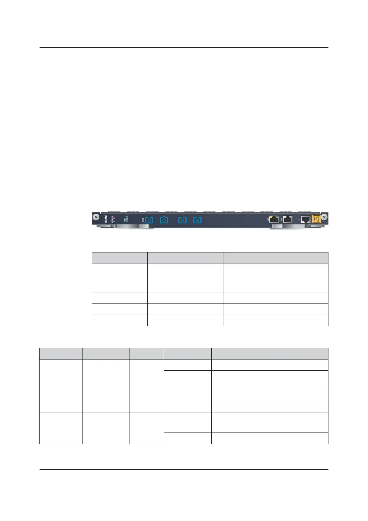
3.13.4 ODMC
Basic Information
Overview of Cards shows the number, matching subracks and power consumption
of the card.
Panel Description
Table 3-98 Interfaces
Identifier
Meaning Description
OTDR 1 to 4
Optical power detection
interface
Connect with the devices to be tested on
the remote end, corresponding to the
remote device one to one.
COM
COM serial port Controls the remote end equipment.
ETH
Commissioning network port
Reserved functional interface
D
Debugging serial port RJ-45 debugging serial port
Table 3-99 Indicator LEDs
Identifier
Meaning
Color Status
Description
ACT
Working
indicator LED
Green
ON
The card is working normally.
Blinking slowly The card is being initialized.
Blinking quickly
The card is receiving a configuration
command.
OFF
The card is not powered on.
ALM
Alarm indicator
LED
Red
ON
The communication between the active and
standby cards fails.
OFF
The card is working normally.
134 Version: C
 Loading...