QUICK START GUIDE
Fidelis Network™ High Capacity Collector
www.fidelissecurity.com ©Fidelis Cybersecurity
Collector Setup Checklist
Fidelis Network Sensor – Appliance Requirements
Appropriate rack space, power, and cooling (Appendix B)
Rack tools, rails, and connectors
Keyboard and video monitor / KVM switch for temporary appliance setup
Power cables — two per appliance, appropriate for power source and region
Ethernet cables (cat5 and optical) for Admin, DB, SYNC and iLO ports (Section 3)
Network switches with enough physical ports (Section 4)
Optical transceivers for switches
Logical network information: IP addresses, hostnames (Section 5, Appendix A)
For Fidelis Network Software version 9.0.5 and later, the appliance system type (Appendix D)
3. Collector: Network Port and Cabling Requirements
Each appliance must be connected to the various networks with appropriate cables and in some
cases, transceivers. The tables below describe the physical connection and cable type associated
with each port on the appliance.
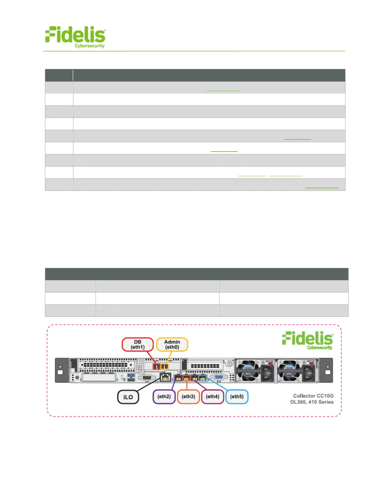
Collector Controller 10G Appliance
Physical Connection Type (default)
Fiber SR Patch Cable, Multimode 850nM
Fiber SR Patch Cable, Multimode 850nM
Figure 3: Network Port Assignments — Collector Controller 10G (Rev-I)