QUICK START GUIDE
Fidelis Network™ High Capacity Collector
www.fidelissecurity.com ©Fidelis Cybersecurity
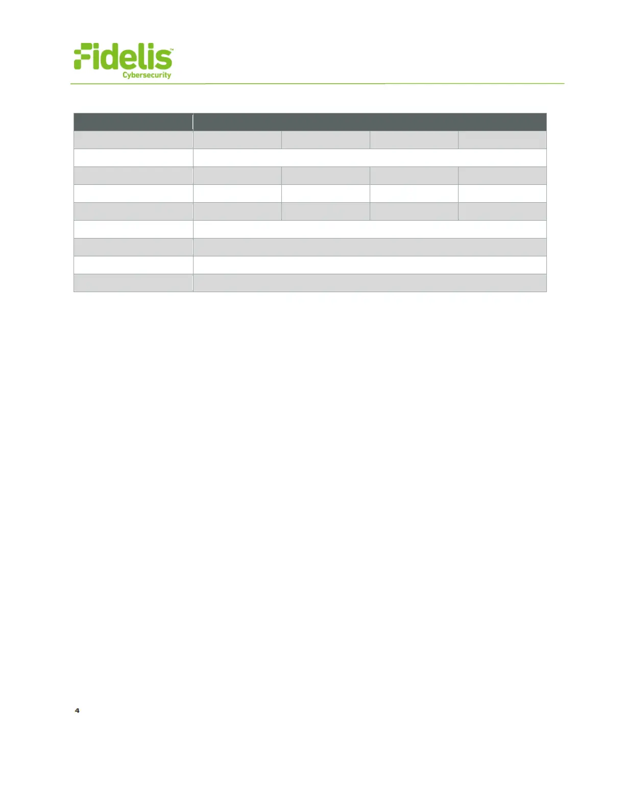
Sample Network Configuration Table
collector-xa1.organization.net.
6. Appliance Installation
Rack Installation
Install each appliance in an enclosure/location that has necessary power and cooling.
Power
Connect power cables to the power supplies in the back of the appliance.
Network Cabling
Using the connectors and cables described in sections 4 and 5, begin to connect the appliances to
the networks. Refer to the Collector network diagram for this section.
Cable the Collector Controller 10G appliance(s) to the switches:
1. Connect Admin (eth0) port to the “ADMIN” switch port
2. Connect DB (eth1) port to the “DB” switch port
3. Connect the iLO port to the ADMIN (or ILO) switch port (optional)
4. Repeat for each Collector Controller.
Cable the Collector XA4 Node appliances to the switches:
1. Connect Admin (eth0) port to the “ADMIN” switch port.
2. Connect DB (eth1) port to the “DB” switch port.
3. Connect SYNC (eth2) port to the “SYNC” switch port.
4. Connect the iLO port to the ADMIN (or ILO) switch port. (optional)
5. Repeat for each Collector XA.