QUICK START GUIDE
Fidelis Network™ High Capacity Collector
www.fidelissecurity.com ©Fidelis Cybersecurity
Collector XA4 Database Node
Physical Connection Type (default)
10GbE SFP+ w/ LC Connector
Fiber SR Patch Cable, Multimode 850nM
10GbE SFP+ w/ LC Connector
Fiber SR Patch Cable, Multimode 850nM
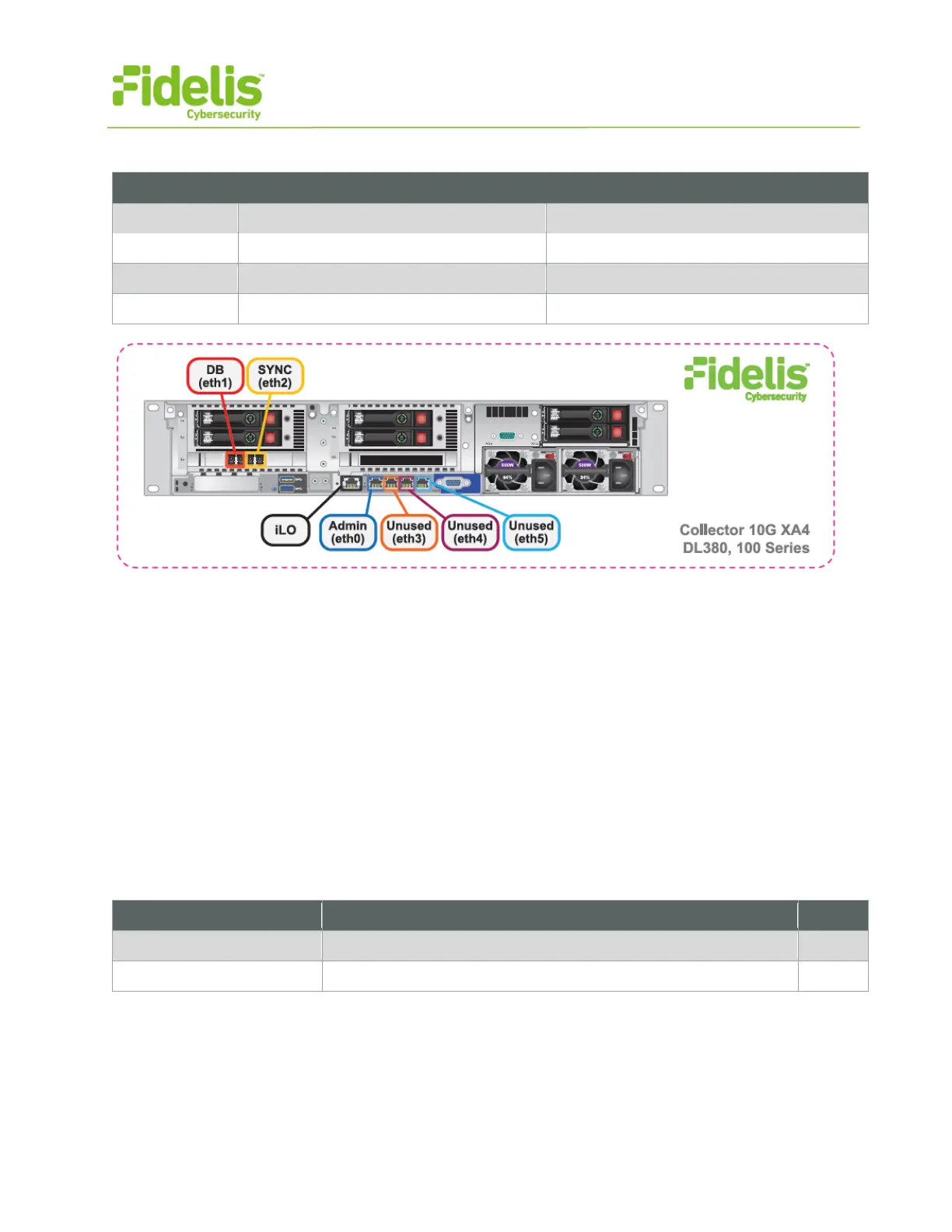
Figure 4: Network Port Assignments — Collector XA4 (Rev-I)
4. Collector Networking Environment
The Collector appliances use multiple networks for service and inter-node communication. Networks
may be deployed as three independent physical switches — or — multiple independent VLANs on
the same switch fabric. The ADMIN, DB, and SYNC switches or VLANs must be different broadcast
domains. (iLO and ADMIN networks may intersect)
Use the tables below to identify the count and type of switch ports necessary to support the number
of appliances for your deployment.
Admin Network
The Admin Network connects the Collector Controller to the Fidelis Network sensors and K2
systems. Also connects the Collector XA nodes to the K2.
10GbE Fiber SR, LC connector (may require SFP+ transceiver)
GbE - Copper Cat5 RJ45 port