page 5 of 12
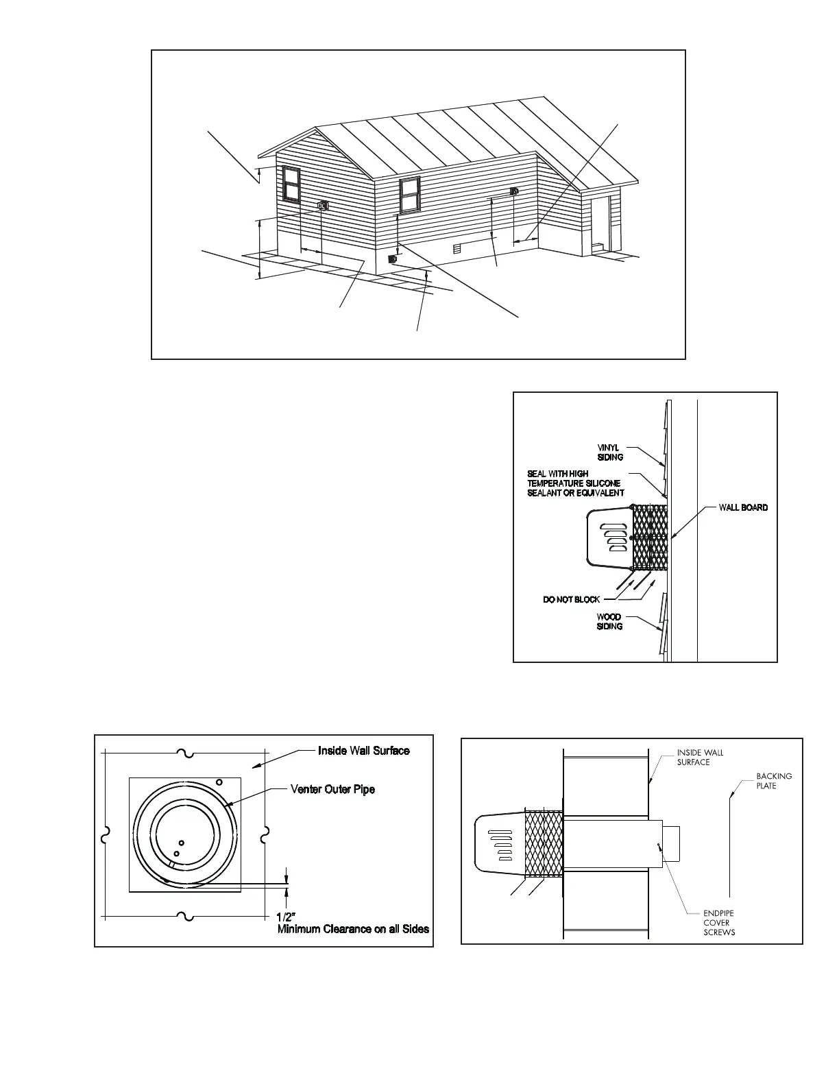
Diagram A
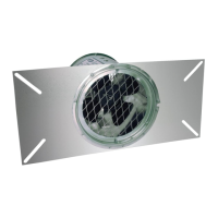
Figure 4
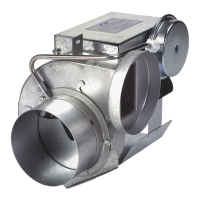
Figure 2
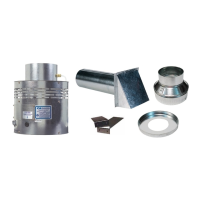
Figure 3
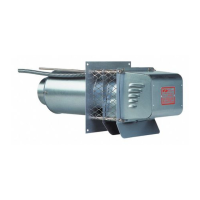
SWG Series Power
Venter Must Be At
Least 1 Foot Above
Doors Or Windows.
SWG Power Venter
Must Be At Least 7
Feet Above Public
Walkways.
SWG Series Power Venter
Must Be At Least 4 Feet To
The Side Of Any Doors Or
Windows.
SWG Power Venter Must Be
Mounted At Least 1 Feet
Above Finished Grade.
SWG Series Power Venter
Must Be At Least 4 Feet Below
Windows.
SWG Series Power Venter
Must Be At Least 3 Feet Above
Any Outside Air Intake Within
10 Feet.
SWG Series Power
Venter Must Be Mounted
At Least 3 Feet From
Inside Corners.
SWG SERIES POWER VENTER INSTALLATION LOCATIONS
NOTE: If mounting the power venter though a combustible wall
material and the ue gas temperature is above 400ºF at the
power venter inlet, line the square hole with a piece of corrosion
resistant sheet metal or non-combustible material. The liner
piece should be the same width as the wall section. (See Figure
3) The power venter has a maximum ue gas temperature of
550ºF at the venter inlet. For installation in wall thicknesses over
8 inches, use SWG Series Through Wall Extension Kit, Model PEK.
4. Backing Plate Installation
Remove the end pipe cover screws on the sides of the outside
pipe and remove end pipe cover. Then mount the backing
plate over the outer pipe and route the exible conduit
and pressure switch tube (if applicable) through the holes
provided in the backing plate. Fasten the backing plate to the
inside wall with appropriate fasteners. (See Figure 4) Re-install
the end pipe cover and screws.
P/N 46139100 Rev P 08/19
 Loading...