The safety PLC (e.g. FPSC) is responsible for the fast speed / slow speed position control and provides
this state to the AKAS® inputs SGO, SGS and SP vis a signal line. (see wiring diagram 1/S. 29)
in fast speed: at SGO, SGS and SP = 0 V
in slow speed: at SGO, SGS and SP = + 24 V
During this, the safety PLC must monitor the signal line to the AKAS® for eventual short-circuits
against potential conductiong lines.
In the operating modes "without additional Safety PLC" the monitoring of the foot pedal is permanently
present. AKAS ® activates the safety outputs OSSDs only if the foot pedal is permanently pressed.
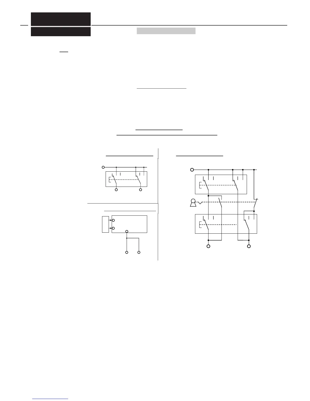
AKAS® monitors both positions of the foot pedal and requires:
if the foot pedal is released: at FUO = +24 V and at FUS = 0 V (see wiring diagram 4a/S. 40)
if the foot pedal is pressed: at FUO = 0 V and at FUS = + 24 V
The monitoring function is able to monitor even 2 connected foot pedals, if two operators work at the
press brake and if the foot pedals are correctly wired as shown in wiring diagram 4b/S. 36.
In the operating modes "with additional Safety PLC" the monitoring of the foot pedal can be cancelled,
by selecting: " equivalent switching inputs for enabling the closing stroke".
In this case, both AKAS® inputs FUS and FUO are triggered + 24 V, if a closing movement of the press
brake is wanted.
During the operating modes without additional safety PLC, a foot pedal response delay of the AKAS®
safety outputs (OSSDs) of about 30 ms after the release of the foot pedal during the fast speed closing
stroke can be selected.
When the foot pedal is checked also by the machine control, the control will execute an easier, smoother
breaking via the proportional valves of the closing movement during this time, just before the OSSDs of
the AKAS® disable the other closing stroke valves.
The overrun traverse control is realized by a cam switch with a normally closed contact. For this, the
length of the cam must correspond to the allowable overrun traverse plus the hysteresis of the cam
switch. The maximum allowable overrun traverse must not exceed the value programmed via the dip
switch positions in the support of the AKAS®-3F and -IIF, respectively the value of 15 mm with the
AKAS®-LCF. This overrun traverse cam must be mounted in a way that the press is in the maximum clo-
sing speed when the cam switch is opened by the cam, and the stroke is started out of the upper dead
center of the machine.
The overrum traverse test is carried out after every voltage reset and must be repeated every 24 hours.
After the successful overrun traverse test, the press must be at first opened for the execution of one ben-
ding stroke. The ajustment controll-LEDs are flashing slowly until the press brake is not opened.
If the overrrun traverse is too long, the cam does not open the overrun traverse cam switch when the clo-
sing movement is stopped, and the AKAS will prevent the complete bending strokes in fast speed.
If the overrun traverse control is not carried out by the AKAS®, the machine control must carry out an
overrun traverse test at least after a voltage reset. This overrun traverse test must be repeated within the
 Loading...