AKAS® monitors in a safe way both positions of the stop- and the fast speed closing state of the contac-
tor position monitors and switching contactors and requires:
in fast speed state at EDMS = + 24 V and at EDMO = 0 V
in Stop state at EDMS = 0 V and at EDMO = + 24 V (see wiring diagram 2/S.39)
During the closing movement in slow speed, EDMO has to be = 0 V, EDMS is not monitored.
After the relase of the safety switching outputs (OSSDs) the AKAS® requires a switch-over of the EDM
signals no later than 300 ms + the programmed tolerance enhancement.
In the operating modes with additional safety PLC (e.g FPSC) the safety PLC must carry out the moni-
toring of the stop contactors.
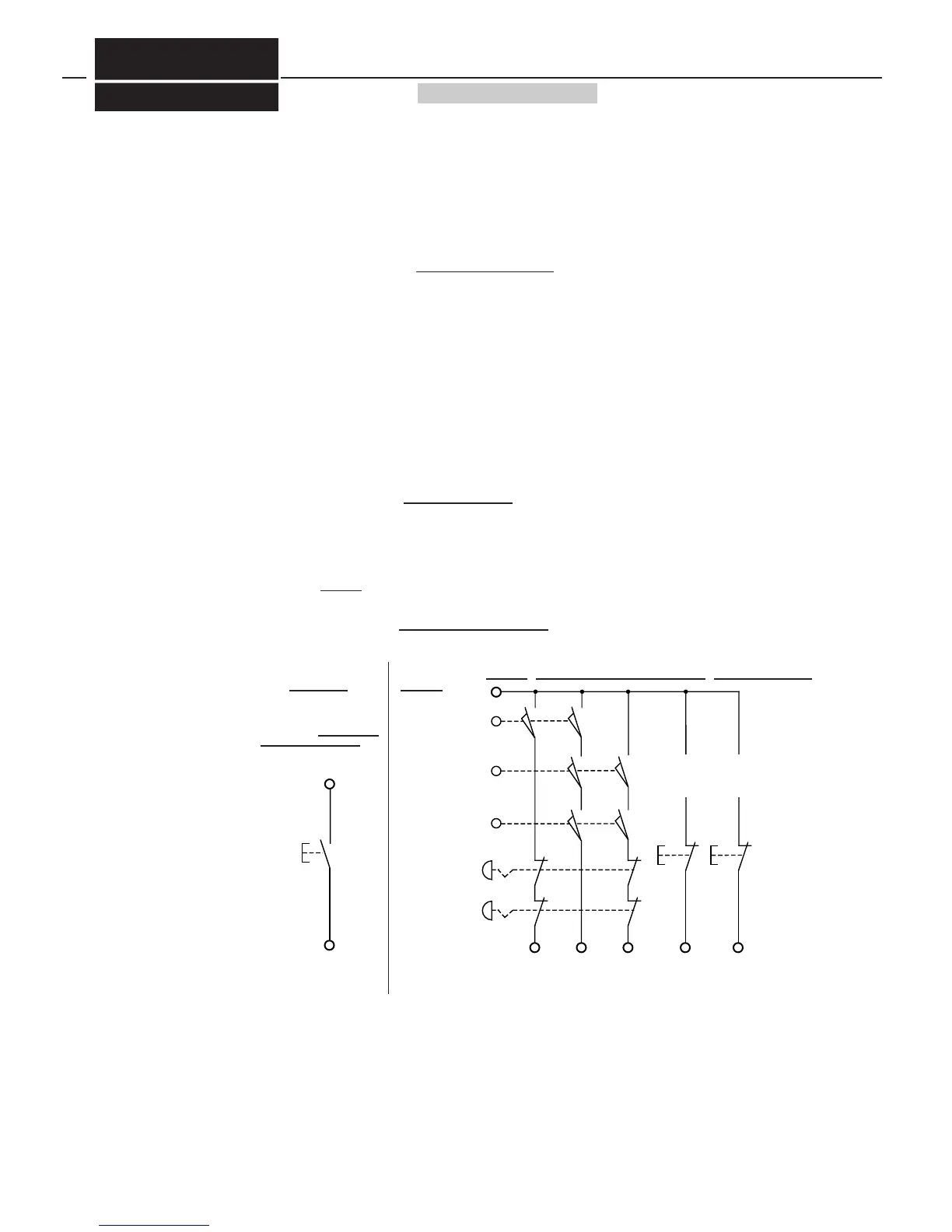
The protective doors and the emergency OFF-buttons are evaluated by double-channel inputs. As soon
as at least one inout is disab led, i.e. is in OFF state, the closing movement will be stopped immediately
by switching OFF of the OSSDs, and the movement of the rear stoppers is prevented by the disabling of
the double channeled release RXOK1 and RXOK2. A continuation of the press operation in only possi-
ble if all relevant protective switching circuits are disabled and and then closed again, and if afterwards
the respective rest button is activated.
If the protective side doors are opened, AKAS® permits the movement of the rear stoppers after ha-
ving activated the respective reset button. The closing movement of the press is permitted only during
slow speed state. For this, AKAS® requires the prevention of the fast speed by the NC, by disabling the
output SGA . AKAS® monitors the slow speed state during the closing movement. During this, the pro-
tective field of the AKAS® is not active.
During operation with foot pedal monitoring (antivalent foot pedal contacts) , the reset is carried out after
the disabling and re-enabling of the Emergency-OFF-Circuits and of the lateral protective metal grids.
This is carried out by activation of an normally closed contact butto., which is connected in series to the
normally closed foot pedal contact at FUO (see wiring diagram 2/S.39 u. 5b/S.41) .
The Reset after the disabling and re-enabling of the rear protective grid is carried out during the opera-
tion with EDM by activation of a normally closed contact button, which is connected in series to the nor-
mally closed contactor controls at EDMO. (see wiring diagram 5a/S.41).
During the operation without foot pedal monitoring (equivalent triggering of FUO and FUS ) the reset of
all protective circuits is carried out by a normally open contact which is connected between + 24 V and
EDMO. (see wiring diagram 5a/S.41)
The ermegency-OFF-circuits are equivalent switching, i.e. the eemergenca-OFF-buttons must have 2
normally closed contacts. When laying out the circuits of the protective doors, you may choose from eit-
her the equivalent switching protective door contacts, i.e. 2 normally open contacts per door switch, or
antivalent switching contacts, i.e. only one normally open and normally closed contact per door switch.
The secons possibility, however, is only available with the operation modes without additional safety
PLC. The connection of the emergeny OFF- circuits and the equivalent protective door contacts to the re-
set buttons when EDM is selected, is shown on wiring diagram 2/S.39.


 To Next Page