Document No. 26-0947 Issue 12
Subject to change
This document is only intended to be a guideline and is not applicable to all
situations. Information subject to full disclaimer at www.ke.com/disclaimer
INSTALLATION AND MAINTENANCE
INSTRUCTIONS
http://www.ke.co.uk/
resource-downloads/twinex/
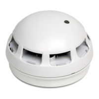
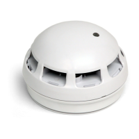
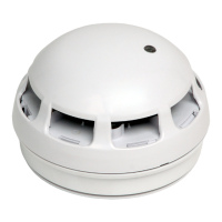
General Description
The Twinex Multipoint ASD is a plug-in type smoke detector that utilises a photo-electric sensing chamber
to make a measurement corresponding to smoke density. The device also incorporates a thermistor
sensing circuit to allow for accurate heat measurement. These elements allow the device to be congured
to a smoke, heat or combined setting. This device is only compatible with the Twinex control panels (and
their associated detection and alarm equipment) and may also incorporate a sounder beacon (ignore all
references to sounders/beacons if your device has no sounder/beacon).
Before Installation
The detector must be installed in compliance with the control panel installation manual. The installation
must also meet the requirements of any local authority.
Spacing
Fike recommends spacing detectors in accordance with any local authority. Due to the eects of IR and possible magnetic
interference, detectors should not be tted any closer than 500mm (preferably 1000mm) to a light tting or any other source of IR or
EMI. In addition to this recommendation the device should be mounted so that the indication LED is facing towards the light tting.
For more specic information regarding detector spacing, placement and special applications please refer to local authority.
Note: As with other optical detectors, this device should not be located where subjected to high levels or pulses of light or infra red
light, as this may cause false alarms or faults.
Device Installation
All wiring must be installed in compliance with the recommendations laid out by any local authority as well as any special
recommendations documented in the control panel installation manual. The cabling used should be of a 2-core 1.5mm2 screened,
re resistant type (e.g. FP200 equivalent), and is to be wired in the form of a screened 2-core radial circuit (with no spurs) from the
control panel, terminating at the last (“End of Line”) device.
Fix the detector base in a suitable horizontal position using the two screw slots provided, remembering to allow enough cable length
for termination. You may then terminate your cables directly into the terminal block according to the terminal labels. It is important to
maintain the screen continuity in order to protect against data corruption from interference.
Please note that the Multipoint ASD may not be compatible as the End of Line device for older V3 Twinex
Panels.
204-0003 Twinflex Multipoint ASD Detector
204-0001 Twinflex Multipoint ASD with Sounder
204-0012 Twinflex Multipoint ASD with Sounder / Strobe
Terminal Description
1 REM LED - REMOTE LED 0V (-VE)
2 ZONE + ZONE IN/OUT +VE & REMOTE LED +VE
3 0V ZONE IN/OUT 0V
4 NOT FITTED N/A
5 NOT FITTED N/A
SCRN SCRN SCREEN