Document No. 26-0947 Issue 12
Subject to change
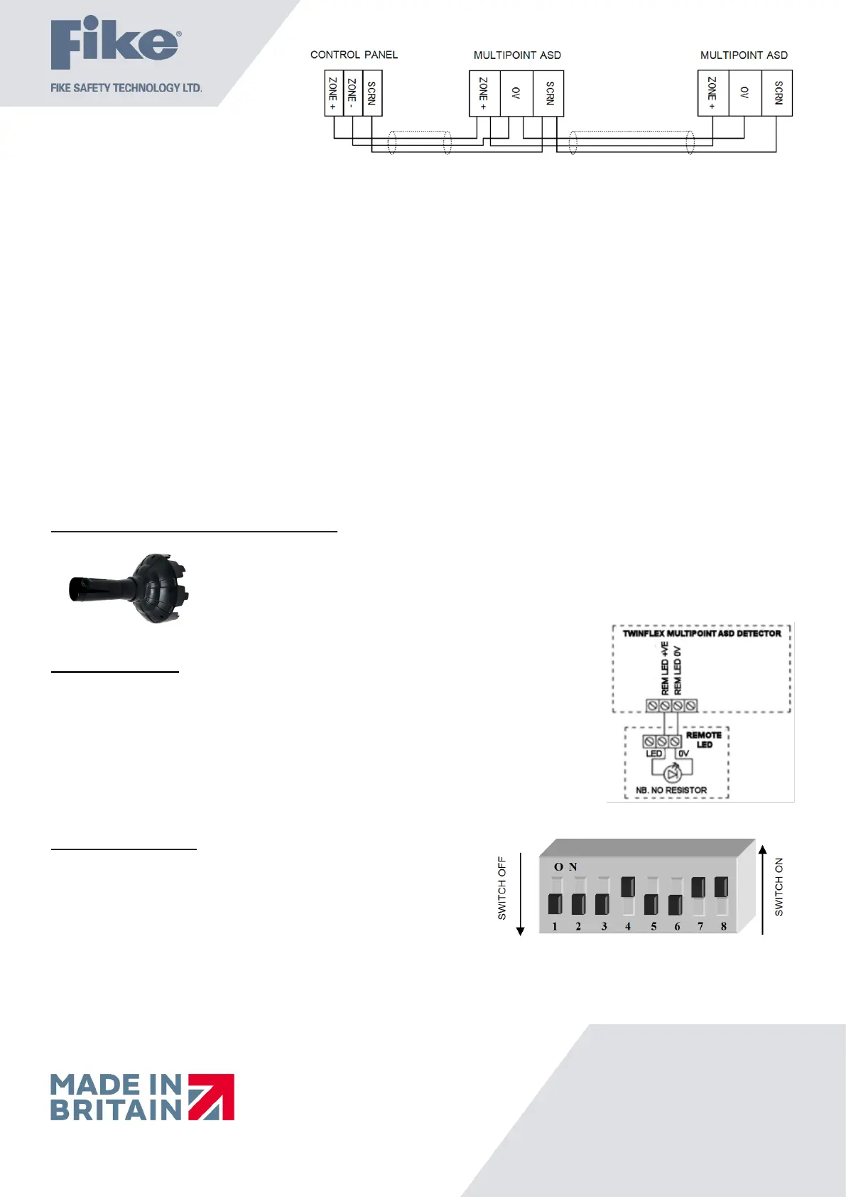
Twinex Multipoint ASD Detectors can be mixed on the same zone as other types of Twinex device (e.g. Twinex Call-points and
earlier detectors). If mixed with earlier detectors, the zone must be set to ‘CP/DET’ and not ‘CP/SM/HT’. The above diagram shows
how to make the zone positive, zone negative and screen connections between the control panel and Twinex Multipoint ASD
Detectors. Refer to the instruction leaets supplied with other Twinex devices for their equivalent wiring/terminal labelling details.
Please note that the SCRN terminal on the detector bases should only be connected to the zone cable screen and NOT to the building
earth. The cable screen is connected to earth at the panel end only, via the zone “SCRN” terminal (or EARTH terminal on the Twinex
V3 2/4/8 Zone panels). It is important to maintain the screen continuity in order to protect against data corruption from interference.
Please remember that all high voltage testing must be carried out before the installation of the detector base or electronics, as this
will cause damage (a small electronics module is also present in base). Once all testing has been carried out on the cabling and
‘continuity & integrity’ has been proven, the detection base & head may be tted. Before tting the detector head program the device
settings via the on-board DIL switches, remembering to set the EOL for the last device.
Remember that the device at the end of the line must have its EOL signal activated using the relevant DIL switch. Do not use a
resistor or capacitor (or another manufacturer’s End of Line device) as the end of line, as this may prevent correct operation of the
zone.
To install the detection head, locate the pins and gently twist until the unit locks in place.
Tamper Resistance and Head Removal
The ASD detector incorporates a tamper resistant locking mechanism that prevents its removal from
the base without the use of a special tool. To remove the device, the tool should be attached over the
detector and turned anti-clockwise allowing the detector to be removed from the base.
Remote Indicator
The remote LED terminals (‘Remote LED + / -’) may be used to connect a separate LED
(Pt No. 600-0092). The LED functions are as follows:
• 5ms every 5 seconds: End of Line
• 5ms every 1.3 seconds: Fault
• 350ms every 0.7 seconds: Fire detected by detector
• Continuous: Fire detected by detector and processed at panel
• 100uS pulse every 20seconds in standby (2 pulses if set to heat)
Note that the LED does not require a resistor.
DIL Switch Settings
The detector DIL switches may be used to program the operation of the
Multipoint ASD Detector. They may be altered when the device is removed
from the base. If a heat detection mode is selected then use the ‘HEAT’ labels
supplied to label the base of the detector clearly.
The last device on the circuit must have the EOL signal enabled
(switch number 1 in the ‘ON’ position).
If the Multipoint ASD Detector is used with the SRP panel, DIL switch 2 must be set in the OFF position,
(Logical Link OFF). DIL switches 6 must be ON & 7 must be OFF, (for continuous sound pattern).
The SRP panel controls the sound pattern so if the Multipoint ASD Detector is set to anything
other than continuous sound it will conict with the SRP panel.
 Loading...