1
SERIES FR702VR
115 and 230 VOLT AC
FUEL TRANSFER PUMP
Owner’s Operation & Safety Manual
Models FR702VR & FR702VER
OUTSTANDING FEATURES
•Up to 18 GPM/68 LPM
•UL listed dispenser & motor
•Full 1/3 HP explosion proof motor
•Meter accuracy
of ±
1%
GENERAL DESCRIPTION
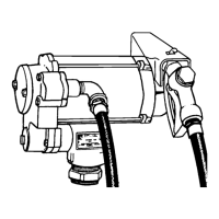
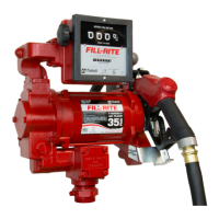
The FR702VR compact cabinet pump is based on Fill-Rite’s
FR700V positive displacement, direct drive pump, and Fill-Rite’s
series 800C nutating disc flow meter which features a flow rate of 5
to 20 GPM or 19 to 76 LPM and is accurate to within ± 1%.
Depending on product viscosity and nozzle selection, the FR702VR
can deliver up to 18 gallons/68 liters of fluid per minute. This
pumping system is UL listed for use with gasoline and diesel fuel.
The U.S. gallon meter has three resettable wheels, two unit wheels
and a tenth wheel. Its non-resettable totalizer has five unit wheels
and a tenth wheel. The optional liter meter has three unit wheels
which can be reset to zero. Its non-resettable totalizer has six unit
wheels.
OPTIONS
• Automatic nozzles
• Metering in U.S.
gallons or liters
•
Red or
white cabinet paint
• Pedestal for island installations
•
220 VAC, 50/60
Hz
TECHNICAL INFORMATION
Design Features:
• 1.25" NPT inlet, 3/4" NPT outlet
• 22 PSI maximum outlet pressure
• Minimum dry vacuum of 10" Hg
• Furnished with 3/4" dia. x 12' hose and manual nozzle
•
Cabinet measures 13"W x 11.5"D x 17.5"H (38 x 29 x
43.6 cm)
•
Built-in check valve, bypass valve and thermal exp
ansion
valve
•
No additional foot valve or check
valve needed to hold
prime
•
1/3 HP 115VAC-60Hz, 5.5 amp, 1725 RPM, direct
drive
motor
•
Ball bearing construction: no lubrication required
• Thermal overload protection
•
Explosion
proof
•
Meter’s mechanical totalizer to 100,000 units
•
Meter accuracy is ± 1%
• Unit wheels have large 11/16" (18 mm) figures
• Convenient, large reset knob with positive zero stop
• Not for
resale use
• Pre-installed Anti-Siphon Valve
FLUID COMPATIBILITY
If in doubt about compatibility of a specific fluid, contact supplier of
fluid to check for any adverse reactions to the wetted materials in
the parts list.
SAFETY INSTRUCTIONS
To ensure safe and efficient operation, it is essential to read and
follow each of these warnings and precautions.
1.
Improper use or installation of this product can caus
e serious
bodily
injury or death.
2.
Do NOT smoke near pump or use pump near an
open flame
w
hen pumping flammable fluids. Fire could result.
3.
A Fill-Rite filter should be used on pump outlet to en
sure that
no foreign mate
rial is transferred to
fuel tank.
4.
Use gasoline and oil resistant thread sealant or se
alant tape
on all threaded jo
ints to protect ag
ainst leakage.
5.
Storage tank should be anchored to prevent tipping
in both the
full and empt
y co
nditions.
6.
To minimize static electricity buildup, only use static wi
re,
conductive hose w
hen pumping fl
ammable fluids and keep
nozzle in contact
with container being filled wh
ile filling
container.
7.
The pump motor is equipped with thermal overload
protection.
If overheated, it
will shut off without any damage to
the
w
indings. Be sure to turn off the pump powe
r if this occurs.
When the moto
r cools, it will restart without warnin
g if power is
on.
8.
Take motors needing service to an authorized repa
ir shop to
maintain “explosion proof
” and “rain proof” integrity.
9.
Do not operate without the check valve (700F2661
) in place.
Fluid leakage could result.
DANGER
Electrical wiring should be done by a licensed electrician in
compliance with local, state and national electric codes,
NEC/ANSI/NFPA 70, NFPA 30, NFPA 30A, as appropriate to the
intended use of the pump. Threaded rigid conduit, seal fittings and
conductor seal should be used. Pump should be properly grounded.
Improper use or installation of this product can cause serious bodily
injury or death.
WARNING
Do not use this product for fluid transfer into aircraft. This product is
not suited for use with fluids for human consumption or fluids
containing water.
INSTALLATION
GENERAL
Pumps are furnished with a tank adapter for skid tank mounting;
pedestals are available for island installations. All tanks must be
properly vented. A pressure retaining vent/fill cap can be used to
reduce fuel loss due to evaporation but will reduce flow rate.
Fill-Rite filters are recommended when pumping fuels.
Pump has a built-in check valve with pressure relief to prevent fluid
thermal expansion from causing unsafe system pressures. Do not
use additional check valves or foot valves unless they have a
proper pressure relief valve built into them. Additional check
valves will reduce flow rate.
Use a gasoline and oil resistant pipe sealant on all pipe threads to
protect against leaks.
SKID TANK MOUNTING
1. Cut a 1-1/4" pipe that will extend to at least 3" (8 cm) above
bottom of tank
when screwed into tank adapter and
tank
adapter is scre
wed into tank flang
e.
2.
Screw pipe into tank adapter, then screw tank ada
pter into
tank flange.
3.
Mount pump on tank adapter.