Patent Pending
Note: All power connections to be installed to local/national codes by a Certified Electrician. Finelite, Inc. • 30500 Whipple Road • Union City, CA 94587-1530 • (510) 441-1100 • Fax: (510) 441-1510 • www.finelite.com
6 of 13
© 2018 FINELITE, INC. ALL RIGHTS RESERVED. Form CE - 98532. 03/18
HP-2 / HP-4 / HP-6 Recessed or Regressed Spackle & Visible Flange Mitered Corner
Installation Instructions
This is a hypothetical build to show the capabilities of this luminaire family and mount type. Your build may vary.
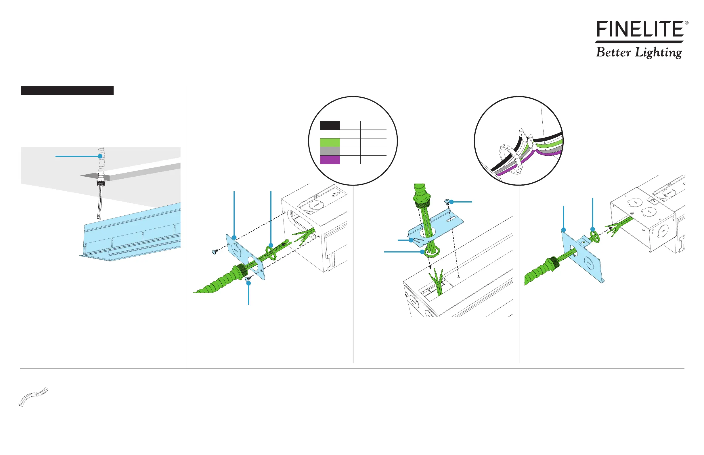
Step 4 - Mounting Starter to Structure
• While properly supporting luminaire, maneuver luminaire near
wall/ceiling opening.
• Make electrical connections at ENDCAP, at TOP or with a
SPLICE BOX.
Jam Nut
Jam Nut
Conduit Plate
#8 Screw
Conduit Plate
#8 Screws
Jam Nut
Conduit Plate
Starter
Conduit
CONTINUED
CONDUIT PLATE - ENDCAP
• Remove two screws holding conduit plate.
• Install conduit and jam nut onto conduit plate.
• Wire-nut electrical connections. See wiring legend above.
• Reinstall conduit plate and screws. Do not damage any wires.
CONDUIT PLATE - TOP (HP-4 ONLY)
• Remove screw holding conduit plate.
• Install conduit and nut onto conduit plate.
• Wire-nut electrical connections. See wiring legend above.
• Reinstall conduit plate and screw. Do not damage any wires.
SPLICE BOX (OPTIONAL)
• Lift tab to unsnap and remove splice box cover.
• Install conduit and nut onto splice box cover.
• Wire-nut electrical connections. See wiring legend above.
• Reinstall splice box cover. Do not damage any wires.
Wire-nut electrical
connections.
(Typical for all options.)
WIRING LEGEND
Black Hot Line Voltage
White Neutral Line Voltage
Green Ground
Grey Dimming 0-10V DC
Purple Dimming 0-10V DC
A. Make Electrical Connections
Flex Conduit
(by others)
Electrical Connection Options
 Loading...